
BMX 70 Electrical Issues - - HELP!!
 Dec 19, 2010 | 03:39 PM
#1

Thread Starter
|
Weekend Warrior
Joined: Dec 2010
Posts: 1
Likes: 0
I just bought a 2007 BMX Mini ATV. The model says it's a 70 cc, but all the tags on the frame and the engine show 107 cc. It is a brand new unit more or less. It has a couple hours on it from the last owner. Their boy was riding it and the battery fell out. It pulled the power wires off.
Here's where I have a problem. No owners manual or electrical diagram.There is no power at the ignition switch, lights, etc. Right now, there is just one hot wire that comes off the battery and it goes to the solenoid. On the other side of the solenoid, the starter wire comes out. Two very small wires come out of the solenoid (they appear to be "sealed" into the top of it) and head into the loom.
For power, that's it. I just can't see how the accessories, lights, and ignition are getting power. It can't be from the two tiny wires that come out of the solenoid leading into the wire loom. Is there supposed to be another wire coming off the "+" of the battery or the "+" side of the solenoid?
I can "jump" the solenoid and it turns over, but without spark.
With no owners manual, I have no idea how the remotes work or what the buttons do. It's hard to even tell what the starter button is on the handlebars!
If you can help or know how to get an owners manual/electrical diagram please share.
Thank you all in advance for the assistance!!
Dec 19, 2010 | 10:30 PM
#2

Electrical Expert
Likes High Voltage In The Tub!
Likes High Voltage In The Tub!
Joined: Dec 2008
Posts: 3,260
Likes: 14
From: Tracy, California, USA
There should be two wires coming off the positive battery terminal. One is a heavy gauge wire that goes to the starter solenoid. The other is a smaller gauge wire that goes to the quad fuse. The other side of the fuse powers everything on the 12 volt bus through the ignition switch (such as headlights, brakelights, and starter motor interlock cicuitry). Sometimes the main fuse is an integral part of the solenoid, and the smaller gauge wire goes off to the ignition switch from the solenoid, but if you don't have a removable fuse embedded in your solenoid assembly then this is not the case on your quad.
I suspect your small gauge battery wire (with an inline fuse) is still pulled off and hanging free somewhere. I'd go looking for it.
The two small wires on the solenoid connect to a small coil inside. When you apply 12 volts across those wires the coil generates a magnetic field which sucks down a steel plate which shorts the two big posts together - just like you did when you jumped the solenoid. They are not an output. You input 12 volts (plus ground) to these wires to make the solenoid work.
I'm going to send you a private message in a few minutes...
May 15, 2011 | 07:31 PM
#3

Weekend Warrior
Joined: May 2011
Posts: 18
Likes: 0
Hello,
I am having the same no spark problem with my BMX 70. After winter storage it wont start. All my wires seam to be connected and in good shape, last year it had trouble with the starter switch on and off so I figured that it finally went that's why I tried arcing the solenoid and still no spark at the plug. I have the plastic all off but need help in how and which order to test the electrical system to find the problem.
Thanks for any help you can provide,
Jeff
May 15, 2011 | 09:34 PM
#4
Electrical Expert
Likes High Voltage In The Tub!
Likes High Voltage In The Tub!
Joined: Dec 2008
Posts: 3,260
Likes: 14
From: Tracy, California, USA
Hello,
I am having the same no spark problem with my BMX 70. After winter storage it wont start. All my wires seam to be connected and in good shape, last year it had trouble with the starter switch on and off so I figured that it finally went that's why I tried arcing the solenoid and still no spark at the plug. I have the plastic all off but need help in how and which order to test the electrical system to find the problem.
Thanks for any help you can provide,
Jeff
I am having the same no spark problem with my BMX 70. After winter storage it wont start. All my wires seam to be connected and in good shape, last year it had trouble with the starter switch on and off so I figured that it finally went that's why I tried arcing the solenoid and still no spark at the plug. I have the plastic all off but need help in how and which order to test the electrical system to find the problem.
Thanks for any help you can provide,
Jeff
 .
.You will a volt meter for the next tests onec we know what CDI you have...
May 16, 2011 | 11:57 PM
#6
Electrical Expert
Likes High Voltage In The Tub!
Likes High Voltage In The Tub!
Joined: Dec 2008
Posts: 3,260
Likes: 14
From: Tracy, California, USA
Is this a picture of your CDI?
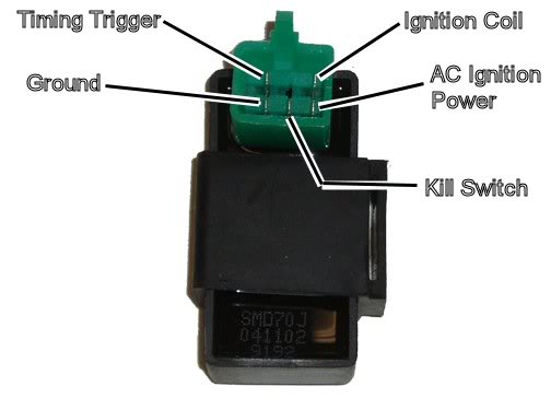
Assuming the answer is yes, the first thing to do is eliminate all kill switches and kill switch wiring:
Method 1) Unplug the CDI and remove the kill switch pin in the CDI connector on the wiring harness. The
pin is held in with a spring tab on the pin itself. You'll have to probe into the connector and push this
tab in order to extract the pin. Plug the CDI back in (kill switch wire dangling) and see if you have
spark.
Method 2) Unplug the CDI. Turn on the ignition switch and set all kill switches to the run position. Use a
meter to measure resistance in of the kill switch pin in the wiring harness connector to engine/frame
ground. If the reistance is infinite on the 100K ohm scale then your kill switches/kill switch wiring are
OK. If you measure zero ohms then you have a kill switch/wiring issue.
The other inputs your CDI needs to make spark are AC Ignition Power, and the Trigger signal. Do the
following:
1) Unplug the CDI. In the wiring connector measure the resistance of the AC Ignition Power pin to the
Ground pin. You should see 400 ohms or so. What do you measure?
2) Measure the resistance of the Timing/trigger pin to the ground pin. You should measure 150 ohms or so.
What do you measure?
3) Leave the CDI unplugged. Set your meter to measure AC volts on the 100 volt scale. Measure the voltage
on the AC Ignition Power pin to the ground pin while cranking the engine. You should see 40 to 80 volts AC
while the engine is cranking. What do you measure?
4) Set your meter to measure AC volts on the lowest scale you have. Ideally this would be 2 volts but many
meters don't go down this low. In that case use the lowest scale you have. Measure the voltage on the
Timing Trigger pin to the Ground pin while cranking the engine. You should 0.2 t0 0.4 volts AC. What do
you measure?
Now for measuring the output side of the CDI:
A) Leave the CDI unplugged. In the CDI wiring connector measure the resistance of the Ignition Coil pin
to the ground pin. You should measure less than 1 ohm (but not zero ohms). What do you measure?
B) Plug the CDI back in. Set your meter to measure AC volts on the 20 volt scale. Set all kill switches
to the run position. Crank the engine while measuring the voltage on the Igntition Coil pin to ground.
Poke through the insulation of the wire if you can't probe the connector.
Caution: There should be moderately high voltage spikes on this wire. Make sure your fingers are not part
of the circuitry. Don't touch the probe lead tips while doing this test.
What you should see is a lot of random numbers with lots of zero values as well. This is because the
meter may catch all or part of the spark event voltage, with a lot of nothing in between. Describe what
you see.
Note: Using a meter to measure this point produces highly variable results depending on the meter. What
you really need is an oscilloscope, but most always a meter is all that is available. We have to do the
best we can with what's available. Describe the meter results as accurately as you can - there is
information there to chew on....
May 18, 2011 | 07:58 PM
#7
Weekend Warrior
Joined: May 2011
Posts: 18
Likes: 0
Lynn,
I will go through all these tests this Sunday and get back to you with my results.
Thanks for all the help,
Jeff
I will go through all these tests this Sunday and get back to you with my results.
Thanks for all the help,
Jeff
Trending Topics
May 18, 2011 | 11:46 PM
#8
Electrical Expert
Likes High Voltage In The Tub!
Likes High Voltage In The Tub!
Joined: Dec 2008
Posts: 3,260
Likes: 14
From: Tracy, California, USA
No sweat. I gave you a lot to chew on. If it gets overwhelming start at the top and go down the list one by one. Check the kill switch and report back problems / questions / results. Then we can discuss and move on to the next step (measuring AC Ignition power). Or do all the tests at the same time if you're comfortable doing that. Small steps or big steps - it's up to you .
.
May 23, 2011 | 02:06 PM
#9
Weekend Warrior
Joined: May 2011
Posts: 18
Likes: 0
Method 1) Unplug the CDI and remove the kill switch pin in the CDI connector on the wiring harness. The
pin is held in with a spring tab on the pin itself. You'll have to probe into the connector and push this
tab in order to extract the pin. Plug the CDI back in (kill switch wire dangling) and see if you have
spark. Still no spark.
The other inputs your CDI needs to make spark are AC Ignition Power, and the Trigger signal. Do the
following:
1) Unplug the CDI. In the wiring connector measure the resistance of the AC Ignition Power pin to the
Ground pin. You should see 400 ohms or so. What do you measure? 514
2) Measure the resistance of the Timing/trigger pin to the ground pin. You should measure 150 ohms or so.
What do you measure? 110
3) Leave the CDI unplugged. Set your meter to measure AC volts on the 100 volt scale. Measure the voltage
on the AC Ignition Power pin to the ground pin while cranking the engine. You should see 40 to 80 volts AC
while the engine is cranking. What do you measure? 56
4) Set your meter to measure AC volts on the lowest scale you have. Ideally this would be 2 volts but many
meters don't go down this low. In that case use the lowest scale you have. Measure the voltage on the
Timing Trigger pin to the Ground pin while cranking the engine. You should 0.2 t0 0.4 volts AC. What do
you measure? .3
Now for measuring the output side of the CDI:
A) Leave the CDI unplugged. In the CDI wiring connector measure the resistance of the Ignition Coil pin to the ground pin. You should measure less than 1 ohm (but not zero ohms). What do you measure? 1.7 to 1.9
B) Plug the CDI back in. Set your meter to measure AC volts on the 20 volt scale. Set all kill switches
to the run position. Crank the engine while measuring the voltage on the Igntition Coil pin to ground.
Poke through the insulation of the wire if you can't probe the connector. No reading.
These were my results, I'm hoping that the no reading on the last one is narrowing things down. My brother helped me and we suspect the coil or the CDI itself?
Thanks again,
Jeff
May 23, 2011 | 11:24 PM
#10
Electrical Expert
Likes High Voltage In The Tub!
Likes High Voltage In The Tub!
Joined: Dec 2008
Posts: 3,260
Likes: 14
From: Tracy, California, USA
My responses embedded in red...
Method 1) Unplug the CDI and remove the kill switch pin in the CDI connector on the wiring harness. The
pin is held in with a spring tab on the pin itself. You'll have to probe into the connector and push this
tab in order to extract the pin. Plug the CDI back in (kill switch wire dangling) and see if you have
spark. Still no spark. So it's not the kill switch input for sure...
The other inputs your CDI needs to make spark are AC Ignition Power, and the Trigger signal. Do the
following:
1) Unplug the CDI. In the wiring connector measure the resistance of the AC Ignition Power pin to the
Ground pin. You should see 400 ohms or so. What do you measure? 514 OK when coupled with the AC voltage measured below...
2) Measure the resistance of the Timing/trigger pin to the ground pin. You should measure 150 ohms or so.
What do you measure? 110 OK
3) Leave the CDI unplugged. Set your meter to measure AC volts on the 100 volt scale. Measure the voltage
on the AC Ignition Power pin to the ground pin while cranking the engine. You should see 40 to 80 volts AC
while the engine is cranking. What do you measure? 56 Good
4) Set your meter to measure AC volts on the lowest scale you have. Ideally this would be 2 volts but many
meters don't go down this low. In that case use the lowest scale you have. Measure the voltage on the
Timing Trigger pin to the Ground pin while cranking the engine. You should 0.2 t0 0.4 volts AC. What do
you measure? .3 Fine, but make sure this is consistent, and that the meter reads zero when not cranking the engine.
Now for measuring the output side of the CDI:
A) Leave the CDI unplugged. In the CDI wiring connector measure the resistance of the Ignition Coil pin to the ground pin. You should measure less than 1 ohm (but not zero ohms). What do you measure?1.7 to 1.9 This sounds high to me, but I haven't measured every coil out there. It would be a much easier call if it read 20 ohms, or open...
B) Plug the CDI back in. Set your meter to measure AC volts on the 20 volt scale. Set all kill switches
to the run position. Crank the engine while measuring the voltage on the Igntition Coil pin to ground.
Poke through the insulation of the wire if you can't probe the connector. No reading. By "no reading" I assume you mean zero volts. If so, then this is a quandry. If the CDI is getting triggered by the stator, and the coil is not shorted to ground you should measure something here as the meter captures some or all of the ignition pulse to the coil primary. Zero volts suggests that you are not getting the CDI triggered (or the CDI is bad). I would definately recheck the trigger voltage to make sure you are getting the 0.3 volts AC cranking (and zero volts when not cranking). Then I would suspect the CDI. But the coil primary is reading high resistance also. This isn't clear cut.
If you verify the trigger voltage again then I would try changing the CDI first, then the coil.
These were my results, I'm hoping that the no reading on the last one is narrowing things down. My brother helped me and we suspect the coil or the CDI itself?
Thanks again,
Jeff