
No spark issue with lonchin 110cc
 Nov 30, 2011 | 03:15 PM
#1

Thread Starter
|
Weekend Warrior
Joined: Nov 2011
Posts: 22
Likes: 0
As the title I have no spark at my atv.. I belive it is a yamoto. I know for sure it is a lonchin engine 110cc. "halfautomatic" and el start.
the question is how to get this one spark the easiest way. in first i dont need any kill switches, they have to come after i get spark..
the preaviously owner gave it up as he couldnt get spark, and now its my turn to try.
He bought a new cdi and magneto stator without luck. I dont even know if he has accuired the right parts.
It is a 5 pin cdi and a magneto stator w\ 5 wires. yellow, white\blue, white, green and black\red.
I have no idea whitch wire goes were exept green is ground.
Is there someone who could be so kind and help me with this project?
heres a pic of magneto stator and cdi
 Dec 1, 2011 | 12:00 AM
#2

Electrical Expert
Likes High Voltage In The Tub!
Likes High Voltage In The Tub!
Joined: Dec 2008
Posts: 3,260
Likes: 14
From: Tracy, California, USA
You have classic colors at the stator:
Green: ground
Blu/White: Timing Trigger
Black/Red: AC Ignition power
Green: ground (you correctly figured this out already)
White and Yellow wires: Battery charge wires to the voltage regulator. Ignore these for now since they have nothing to do with spark. Later if your battery doesn't keep charged with a running engine we can revisit these wires...
Why do you say you have no idea where thes wires go? Are they disconnected?
Here is the wiring for a 5 pin CDI. This will tell you how the Ground. Trigger and AC Ignition power wires connect up.
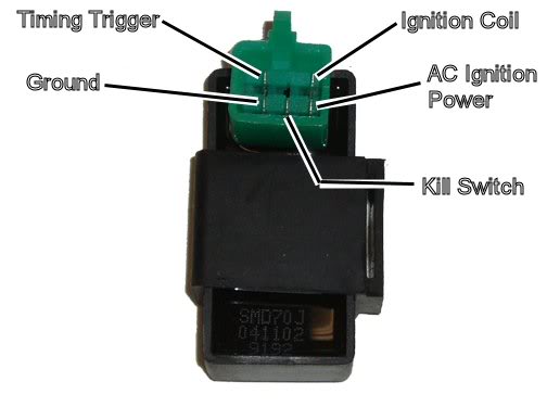
Yes you do need kill switches (at least one anyway). If the quad starts you need to shut it down somehow. 5 pin CDI's run off AC power from the stator, which will delever the required power as long as the engine is running. If you don't have a kill connection the quad will continue running even if you unbolt the battery and remove it.
Is you CDI connector wired up with all the wires, or are they disconnected too?
Green: ground
Blu/White: Timing Trigger
Black/Red: AC Ignition power
Green: ground (you correctly figured this out already)
White and Yellow wires: Battery charge wires to the voltage regulator. Ignore these for now since they have nothing to do with spark. Later if your battery doesn't keep charged with a running engine we can revisit these wires...
Why do you say you have no idea where thes wires go? Are they disconnected?
Here is the wiring for a 5 pin CDI. This will tell you how the Ground. Trigger and AC Ignition power wires connect up.
Yes you do need kill switches (at least one anyway). If the quad starts you need to shut it down somehow. 5 pin CDI's run off AC power from the stator, which will delever the required power as long as the engine is running. If you don't have a kill connection the quad will continue running even if you unbolt the battery and remove it.
Is you CDI connector wired up with all the wires, or are they disconnected too?
Dec 1, 2011 | 10:38 AM
#3
Thread Starter
|
Weekend Warrior
Joined: Nov 2011
Posts: 22
Likes: 0
Thanks for replay lynn. I have come a bit further with my "wirethinking". the blue\white is trigger signal for the cdi. I assume the wire goes in the upper left corner) the black\red is constant power to cdi, whitch goes into "ac ignition power" (lower right corner). can i earth both green wires from cdi and magneto stator in the frame? the black\yellow from cdi (upper right) to ignition coil. the coil is grounded with the bolts directly in frame, and dont need wire ground, right?
the cdi is not connected to the harness.
I understand that I need a kill switch for turning of the engine, but that I can wire up a switch on the black\yellow wire that goes to coil, after i get spark.
is the 5 pin cdi always wired as the picture above? probably stupid question,but are you shure that I have ac volts?
do the middle pin at the bottom need ground or something for determine spark?
thanks in advance
Dec 1, 2011 | 11:33 PM
#4
Electrical Expert
Likes High Voltage In The Tub!
Likes High Voltage In The Tub!
Joined: Dec 2008
Posts: 3,260
Likes: 14
From: Tracy, California, USA

This puts a lot of strain on the CDI, and isn't that good for the switch either. When you turn off the quad this way enormous currents flow while the CDI storage capacitor (the "C" in the "CDI" acronym) dumps all of its energy unrestrained into the switch contacts, and through the CDI output switching transistor. This is really bad design practice.
What is wrong with using the kill switch input to the CDI? You ground that pin with a switch (just like you propose to do with the CDI output) to kill spark. When you ground the kill switch input the spark is killed without drawing enormous current pulses across the switch contacts, and doesn't strain anything else inside the CDI. That's why the original designers at Honda (which was later copied by the chinese) put the kill switch pin there in the first place...
I have never seen a 5 pin CDI like the one pictured earlier that was powered by anything other than moderately high voltage AC from the stator.
Dec 2, 2011 | 10:15 AM
#5
Thread Starter
|
Weekend Warrior
Joined: Nov 2011
Posts: 22
Likes: 0
first of all thanx for a very good and informative answer I will give the wiring as you proposed a try this evening, and we`ll se if its works.
I see your point with shorting the signal before cdi or in the kill switch connection in the cdi, and i will do it in the middle lower pin in the cdi, no reason to think I`m smarter than Honda engineers
I dont have the plastic plug with wires that goes in the cdi, but can I wire them up like the cdi above? mine cdi has a white connector pin instead of green as the picture above if that important.
I will give the wiring as you proposed a try this evening, and we`ll se if its works.I see your point with shorting the signal before cdi or in the kill switch connection in the cdi, and i will do it in the middle lower pin in the cdi, no reason to think I`m smarter than Honda engineers
I have never seen a 5 pin CDI like the one pictured earlier that was powered by anything other than moderately high voltage AC from the stator.
Dec 2, 2011 | 10:36 AM
#6
Electrical Expert
Likes High Voltage In The Tub!
Likes High Voltage In The Tub!
Joined: Dec 2008
Posts: 3,260
Likes: 14
From: Tracy, California, USA
You can just solder the wires directly to the CDI pins. Those pins go to a Printer Circuit Board (PCB) buried down in the black potting compound, so you want to be quick and clean when soldering the wires to the pins. You don't want to heat things up to the point that the solder connection down at the PCB also melts. This caution only applies to someone with *really* ham-handed soldering skills though. The PCB is all the way down at the bottom of the potting cup, with the components facing up toward the connector, so the connector pins are over an inch long. If you can solder each wire onto the corresponding CDI pin in under 10 seconds you will be fine.
Dec 3, 2011 | 04:14 AM
#7
Thread Starter
|
Weekend Warrior
Joined: Nov 2011
Posts: 22
Likes: 0
I have now wired it up as we agreed on, and I get a good spark , the enine runs fine, now I just have to wire up a kill switch. I`m going to use the ignition key to that. Can I connect one wire to the center pin in the cdi, and ground the other wire?.
For getting spark I had to get a new cdi, with green connector and I wired it up as shown above, I guess the old one was bad.
all in all a great evening in the garage
, the enine runs fine, now I just have to wire up a kill switch. I`m going to use the ignition key to that. Can I connect one wire to the center pin in the cdi, and ground the other wire?.For getting spark I had to get a new cdi, with green connector and I wired it up as shown above, I guess the old one was bad.
all in all a great evening in the garage
Trending Topics
 Dec 3, 2011 | 08:31 PM
#9
Electrical Expert
Likes High Voltage In The Tub!
Likes High Voltage In The Tub!
Joined: Dec 2008
Posts: 3,260
Likes: 14
From: Tracy, California, USA
Generic chinese ignition switches have four wires, and two separate switches in them ganged together on a common shaft. The two switches operate as described above. The kill switch side (the two wires that are shorted together when the ignition switch is turned off) are usually black/white and green. Use a meter to verify which wires they really are on your specific switch.
Sep 5, 2014 | 10:08 AM
#10

Weekend Warrior
Joined: Sep 2014
Posts: 5
Likes: 0
Hello,
I have a ATV, brand nmae is AEON COBRA2-R100.
I just noticed recently that my battery ran down, and can not anymore use teh electric starter to fire up the engine. After series of checkings with multimeter, I noticed that the output of the rectifier/regulator (red wire then hooked to the battery terminal with a fues), only reads 6.8 volts, my battery is 12 volts. The plug and socket for the rectifier and the one from the generator side was intact, no loose connection. Where can be the problem? is it on the ac generator itself which gave me a reading of about for only 6 volts? or the rectifier?. Parts here in Kuwait are scarce, so before I will order one if a defective part is sure, I will first check the suspected parts. Thanks in advance. By the way, my ac generator wirings are WHT-Red, BLK-Red, WHT , Y-R, BLACK. (5 wires).