
chinese 110 bigfoot quad no spark
 Jan 7, 2012 | 04:08 PM
#1

Thread Starter
|
Weekend Warrior
Joined: Jan 2012
Posts: 2
Likes: 0
Hi there.
Im new to this site and just wondering if any one can help me. i bought a quad for my kids at christmas they only got to use it twice and its packed up. i found the bike had no spark, so after reading up on the internet about it a bit i ordered new parts. now ive replaced the stator magneto, ht coil and lead, cdi unit and the spark plug. i still cant get a spark. ive checked all the wires and block connectors and all have good connections. can any one help me please. my kids are gutted they cant use there christmas present. thanks.
Im new to this site and just wondering if any one can help me. i bought a quad for my kids at christmas they only got to use it twice and its packed up. i found the bike had no spark, so after reading up on the internet about it a bit i ordered new parts. now ive replaced the stator magneto, ht coil and lead, cdi unit and the spark plug. i still cant get a spark. ive checked all the wires and block connectors and all have good connections. can any one help me please. my kids are gutted they cant use there christmas present. thanks.
Jan 8, 2012 | 01:39 AM
#2

Electrical Expert
Likes High Voltage In The Tub!
Likes High Voltage In The Tub!
Joined: Dec 2008
Posts: 3,260
Likes: 14
From: Tracy, California, USA
I'm going to assume you have the generic standard 5 pin CDI. If you do then proceed with the following procedure. If not we need to back up and start again.
You will need a meter to doo all of the tests, but meters are inexpensive and a useful and powerful tool. They are a *lot* more inexpensive than all the parts you've thrown at this problems so far.
I also see you didn't say you did any kill switch tests. Kill switch issues are a common cause of sudden no spark. If you disconnect the kill switch wire (method one below) you can test this part without a meter.
Is this a picture of your CDI?
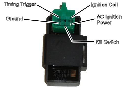
Assuming the answer is yes, the first thing to do is eliminate all kill switches and kill switch wiring:
Method 1) Unplug the CDI and remove the kill switch pin in the CDI connector on the wiring harness. The pin is held in with a spring tab on the pin itself. You'll have to probe into the connector and push this tab in order to extract the pin. Plug the CDI back in (kill switch wire dangling) and see if you have spark.
Method 2) Unplug the CDI. Turn on the ignition switch and set all kill switches to the run position. Use a meter to measure resistance in of the kill switch pin in the wiring harness connector to engine/frame ground. If the reistance is infinite on the 100K ohm scale then your kill switches/kill switch wiring are OK. If you measure zero ohms then you have a kill switch/wiring issue.
The other inputs your CDI needs to make spark are AC Ignition Power, and the Trigger signal. Do the following:
1) Unplug the CDI. In the wiring connector measure the resistance of the AC Ignition Power pin to the Ground pin. You should see 400 ohms or so. What do you measure?
2) Measure the resistance of the Timing/trigger pin to the ground pin. You should measure 150 ohms or so. What do you measure?
3) Leave the CDI unplugged. Set your meter to measure AC volts on the 100 volt scale. Measure the voltage on the AC Ignition Power pin to the ground pin while cranking the engine. You should see 40 to 80 volts AC while the engine is cranking. What do you measure?
4) Set your meter to measure AC volts on the lowest scale you have. Ideally this would be 2 volts but many meters don't go down this low. In that case use the lowest scale you have. Measure the voltage on the Timing Trigger pin to the Ground pin while cranking the engine. You should 0.2 t0 0.4 volts AC. What do you measure?
Now for measuring the output side of the CDI:
A) Leave the CDI unplugged. In the CDI wiring connector measure the resistance of the Ignition Coil pin to the ground pin. You should measure less than 1 ohm (but not zero ohms). What do you measure?
B) Plug the CDI back in. Set your meter to measure AC volts on the 20 volt scale. Set all kill switches to the run position. Crank the engine while measuring the voltage on the Igntition Coil pin to ground. Poke through the insulation of the wire if you can't probe the connector.
Caution: There should be moderately high voltage spikes on this wire. Make sure your fingers are not part of the circuitry. Don't touch the probe lead tips while doing this test.
What you should see is a lot of random numbers with lots of zero values as well. This is because the meter may catch all or part of the spark event voltage, with a lot of nothing in between. Describe what you see.
Note: Using a meter to measure this point produces highly variable results depending on the meter. What you really need is an oscilloscope, but most always a meter is all that is available. We have to do the best we can with what's available. Describe the meter results as accurately as you can - there is information there to chew on....
Jan 8, 2012 | 01:44 PM
#3
Thread Starter
|
Weekend Warrior
Joined: Jan 2012
Posts: 2
Likes: 0
Hi Lynn,
I have ran the tests, method 1 didn't get a spark, method 2 was OK and the other inputs for the CDI at the AC ignition power pin to the ground pin measured 330 ohms. The resistence the timing/trigger pin to the ground pin measured 300 ohms. The AC ignition power pin to the ground while cranking the ignition measured 40 volts. The voltage of the timing/trigger to the ground pin while cranking the ignition measured 2 volts. Now measuring the output side of the CDI. Measuring the resistence of the iginition coil pin to the ground pin measured 0.8 ohms, plugged back in the CDI set all kill switches to ran and cranked the engine. Measuring the ignition coil pin to the ground pin was 12 volts. Any help would be much appreciated.
Gary
Jan 8, 2012 | 10:19 PM
#4
Electrical Expert
Likes High Voltage In The Tub!
Likes High Voltage In The Tub!
Joined: Dec 2008
Posts: 3,260
Likes: 14
From: Tracy, California, USA
Hi Lynn,
I have ran the tests, method 1 didn't get a spark, method 2 was OK and the other inputs for the CDI at the AC ignition power pin to the ground pin measured 330 ohms. The resistence the timing/trigger pin to the ground pin measured 300 ohms. The AC ignition power pin to the ground while cranking the ignition measured 40 volts. The voltage of the timing/trigger to the ground pin while cranking the ignition measured 2 volts. Now measuring the output side of the CDI. Measuring the resistence of the iginition coil pin to the ground pin measured 0.8 ohms, plugged back in the CDI set all kill switches to ran and cranked the engine. Measuring the ignition coil pin to the ground pin was 12 volts. Any help would be much appreciated.
Gary
I have ran the tests, method 1 didn't get a spark, method 2 was OK and the other inputs for the CDI at the AC ignition power pin to the ground pin measured 330 ohms. The resistence the timing/trigger pin to the ground pin measured 300 ohms. The AC ignition power pin to the ground while cranking the ignition measured 40 volts. The voltage of the timing/trigger to the ground pin while cranking the ignition measured 2 volts. Now measuring the output side of the CDI. Measuring the resistence of the iginition coil pin to the ground pin measured 0.8 ohms, plugged back in the CDI set all kill switches to ran and cranked the engine. Measuring the ignition coil pin to the ground pin was 12 volts. Any help would be much appreciated.
Gary

Also your ignition coil voltage of 12 volts is suspicious. 12 volts is only 2 digits, and a meter reading should have more digits than that. This 12 volts was AC voltage? Was it steady, or bouncing around? Your quad battery runs at 12 volts, but your ignition system does not. There is no 12 volt anything in your ignition system. It runs on it's own AC power from the stator which is *completely* separate from the battery. Could you remeasure this and give more detail - like the meter scale, all the digits, and describing in detail any variation in measurements while cranking the engine.

Thread
Thread Starter
Forum
Replies
Last Post
Frisky2050
Buying an ATV
10
Apr 9, 2020 11:19 AM
Currently Active Users Viewing This Thread: 1 (0 members and 1 guests)

