
SUNL 50cc with no spark... HELP.
#1
 04-06-2012, 12:22 PM


Join Date: Apr 2012
Posts: 10
Likes: 0
Received 0 Likes
on
0 Posts
Hello, new to the forum and I have a problem.
Like the Title says I have a SUNL 50cc with no spark. To date I have replace the coil, CDI, and the stator. I have 27vac at the coil wire at the CDI box when the coil is unpluged, when I plug the coil in it the coil wire goes dead. i have checked the Ohms at the coil and I get .6 Ohms from power to ground wires, I get 12 Ohms from sparkplug to ground wires. I have 3 NEW coils and they all have the same readings. I am stumped, I have checked evey inch of wire from the front to rear bumpers and everything looks great. Is there anyone that can help with this problem?
Like the Title says I have a SUNL 50cc with no spark. To date I have replace the coil, CDI, and the stator. I have 27vac at the coil wire at the CDI box when the coil is unpluged, when I plug the coil in it the coil wire goes dead. i have checked the Ohms at the coil and I get .6 Ohms from power to ground wires, I get 12 Ohms from sparkplug to ground wires. I have 3 NEW coils and they all have the same readings. I am stumped, I have checked evey inch of wire from the front to rear bumpers and everything looks great. Is there anyone that can help with this problem?
#2
04-06-2012, 04:08 PM
#3
04-06-2012, 07:49 PM
Join Date: Apr 2012
Posts: 10
Likes: 0
Received 0 Likes
on
0 Posts
Thank you for your reply. Yes I have checked all of them and they are all working as they should. When I trip one of them the whole system shuts down as it should.
The problem I have is the CDI box sends power to the coil and when the coil is hooked up it blows the CDI box. It acts like there is a short on the coil, but I have 3 new coils and they all do the same thing, the newest coil has never been on the ATV. I am at my whits end...
The problem I have is the CDI box sends power to the coil and when the coil is hooked up it blows the CDI box. It acts like there is a short on the coil, but I have 3 new coils and they all do the same thing, the newest coil has never been on the ATV. I am at my whits end...
#4
04-06-2012, 10:42 PM

Electrical Expert
Likes High Voltage In The Tub!
Likes High Voltage In The Tub!
Join Date: Dec 2008
Location: Tracy, California, USA
Posts: 3,260
Likes: 0
Received 13 Likes
on
13 Posts
... I have 27vac at the coil wire at the CDI box when the coil is unpluged, when I plug the coil in it the coil wire goes dead. i have checked the Ohms at the coil and I get .6 Ohms from power to ground wires, I get 12 Ohms from sparkplug to ground wires. I have 3 NEW coils and they all have the same readings....
0.6 ohms on the primary winding is OK, but it is certainly not a "power" wire (as in 12 volts DC...). The voltage here is a very high frequency high voltage "pulse" signal that happens at spark time. It is plus/minus 100 plus volts tall ringing at a frequency of roughly 30,000 times per second.
12 ohms from the spark plug to ground is OK for some quads. For others is is more like 8000 ohms (and all over the map from there). The important point to realize here is that the high tension leads have enormous voltage but very little current. Twelve ohms or eight thousand ohms matters very little, unless you're measuring interferrence to radio and TV signals (higher resistance reduces electromagnetic interference [or EMI]). But this is getting off subject...
How many pins on your CDI? 4? 5? 6? The proper procedure for no spark problems depends a lot on which type CDI you have.....
#5
04-07-2012, 01:59 PM
Join Date: Apr 2012
Posts: 10
Likes: 0
Received 0 Likes
on
0 Posts
Thank you so much for your help, it is clear that I am out of my league. Normaly I am the one that people go to for help, so I am eating a slice of humble pie as I type. lol.
I started with a meter and not finding the reading that I am used to seeing I started replacing parts that I thought might be bad. Wish I would have found this site before I started, could have saved me alot of work and many hours.
I tested every part I replaced and every value was the same from new to old part. The dealer in town here was no help at all for fixing it, but he loves to sell me parts. I wanted to test the parts I was looking at before I bought them to see if they were bad but he would'nt let me.
It is a 5 pin CDI, when I hook up the coil the coil wire goes to 0vac at the CDI box, is that normal? It is clear that I will have to learn this system.
#6
04-07-2012, 08:52 PM
Electrical Expert
Likes High Voltage In The Tub!
Likes High Voltage In The Tub!
Join Date: Dec 2008
Location: Tracy, California, USA
Posts: 3,260
Likes: 0
Received 13 Likes
on
13 Posts
Below is the generic 5 pin CDI procedure for 'no spark' problems. 5 pin CDI's are powered off moderately high voltage AC from the stator, as compared to 4 pin and some 6 pin CDI's which are powered off 12 volt DC. That's why I had to ask which CDI you had.
Start with these tests and post the results. They should narrow down the problem a bit .
.
Start with these tests and post the results. They should narrow down the problem a bit
.
Is this a picture of your CDI?
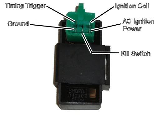
Assuming the answer is yes, the first thing to do is eliminate all kill switches and kill switch wiring:
Method 1) Unplug the CDI and remove the kill switch pin in the CDI connector on the wiring harness. The pin is held in with a spring tab on the pin itself. You'll have to probe into the connector and push this tab in order to extract the pin. Plug the CDI back in (kill switch wire dangling) and see if you have spark.
Method 2) Unplug the CDI. Turn on the ignition switch and set all kill switches to the run position. Use a meter to measure resistance in of the kill switch pin in the wiring harness connector to engine/frame ground. If the resistance is infinite on the 100K ohm scale then your kill switches/kill switch wiring are OK. If you measure zero ohms then you have a kill switch/wiring issue.
The other inputs your CDI needs to make spark are AC Ignition Power, and the Trigger signal. Do the following:
1) Unplug the CDI. In the wiring connector measure the resistance of the AC Ignition Power pin to the Ground pin. You should see 400 ohms or so. What do you measure?
2) Measure the resistance of the Timing/trigger pin to the ground pin. You should measure 150 ohms or so. What do you measure?
3) Leave the CDI unplugged. Set your meter to measure AC volts on the 100 volt scale. Measure the voltage on the AC Ignition Power pin to the ground pin while cranking the engine. You should see 40 to 80 volts AC while the engine is cranking. What do you measure?
4) Set your meter to measure AC volts on the lowest scale you have. Ideally this would be 2 volts but many meters don't go down this low. In that case use the lowest scale you have. Measure the voltage on the Timing Trigger pin to the Ground pin while cranking the engine. You should 0.2 t0 0.4 volts AC. What do you measure?
Now for measuring the output side of the CDI:
A) Leave the CDI unplugged. In the CDI wiring connector measure the resistance of the Ignition Coil pin to the ground pin. You should measure less than 1 ohm (but not zero ohms). What do you measure?
B) Plug the CDI back in. Set your meter to measure AC volts on the 20 volt scale. Set all kill switches to the run position. Crank the engine while measuring the voltage on the Igntition Coil pin to ground. Poke through the insulation of the wire if you can't probe the connector.
Caution: There should be moderately high voltage spikes on this wire. Make sure your fingers are not part of the circuitry. Don't touch the probe lead tips while doing this test.
What you should see is a lot of random numbers with lots of zero values as well. This is because the meter may catch all or part of the spark event voltage, with a lot of nothing in between. Describe what you see.
Note: Using a meter to measure this point produces highly variable results depending on the meter. What you really need is an oscilloscope, but most always a meter is all that is available. We have to do the best we can with what's available. Describe the meter results as accurately as you can - there is information there to chew on....
#7
04-07-2012, 09:40 PM
Join Date: Apr 2012
Posts: 10
Likes: 0
Received 0 Likes
on
0 Posts
Trending Topics
#8
04-08-2012, 08:22 AM
Join Date: Apr 2012
Posts: 10
Likes: 0
Received 0 Likes
on
0 Posts
Is this a picture of your CDI?
Assuming the answer is yes, the first thing to do is eliminate all kill switches and kill switch wiring:
Method 1) Unplug the CDI and remove the kill switch pin in the CDI connector on the wiring harness. The pin is held in with a spring tab on the pin itself. You'll have to probe into the connector and push this tab in order to extract the pin. Plug the CDI back in (kill switch wire dangling) and see if you have spark. No spark
Method 2) Unplug the CDI. Turn on the ignition switch and set all kill switches to the run position. Use a meter to measure resistance in of the kill switch pin in the wiring harness connector to engine/frame ground. If the resistance is infinite on the 100K ohm scale then your kill switches/kill switch wiring are OK. If you measure zero ohms then you have a kill switch/wiring issue.
The other inputs your CDI needs to make spark are AC Ignition Power, and the Trigger signal. Do the following:
1) Unplug the CDI. In the wiring connector measure the resistance of the AC Ignition Power pin to the Ground pin. You should see 400 ohms or so. What do you measure?331 ohms
2) Measure the resistance of the Timing/trigger pin to the ground pin. You should measure 150 ohms or so. What do you measure?4.52 ohms
3) Leave the CDI unplugged. Set your meter to measure AC volts on the 100 volt scale. Measure the voltage on the AC Ignition Power pin to the ground pin while cranking the engine. You should see 40 to 80 volts AC while the engine is cranking. What do you measure?48vac
4) Set your meter to measure AC volts on the lowest scale you have. Ideally this would be 2 volts but many meters don't go down this low. In that case use the lowest scale you have. Measure the voltage on the Timing Trigger pin to the Ground pin while cranking the engine. You should 0.2 t0 0.4 volts AC. What do you measure? 0.18vac
Now for measuring the output side of the CDI:
A) Leave the CDI unplugged. In the CDI wiring connector measure the resistance of the Ignition Coil pin to the ground pin. You should measure less than 1 ohm (but not zero ohms). What do you measure? 0.7 ohms
B) Plug the CDI back in. Set your meter to measure AC volts on the 20 volt scale. Set all kill switches to the run position. Crank the engine while measuring the voltage on the Igntition Coil pin to ground. Poke through the insulation of the wire if you can't probe the connector.
Caution: There should be moderately high voltage spikes on this wire. Make sure your fingers are not part of the circuitry. Don't touch the probe lead tips while doing this test.
What you should see is a lot of random numbers with lots of zero values as well. This is because the meter may catch all or part of the spark event voltage, with a lot of nothing in between. Describe what you see. All zeros, no jumping around. That is what I find weird, when the coil is unplugged it jumps around and will show 27vac, but plugged in it shows 0. That is on the factory coil, the new coils have the same results.
Note: Using a meter to measure this point produces highly variable results depending on the meter. What you really need is an oscilloscope, but most always a meter is all that is available. We have to do the best we can with what's available. Describe the meter results as accurately as you can - there is information there to chew on....
#9
04-08-2012, 12:12 PM
Join Date: Apr 2012
Posts: 10
Likes: 0
Received 0 Likes
on
0 Posts
I wonder if I have a DC CDI box? Is there a difference? I told the dealer it was AC and he said all of the 5 pins were the same, is that true? The onl reading that does not match is the trigger pin to ground, I have 3 of them all came from the same dealer and all have the same readings.
Does that help?
Does that help?
#10
04-08-2012, 09:44 PM
Electrical Expert
Likes High Voltage In The Tub!
Likes High Voltage In The Tub!
Join Date: Dec 2008
Location: Tracy, California, USA
Posts: 3,260
Likes: 0
Received 13 Likes
on
13 Posts
The main thing that sticks out on your measurements is the 4.52 ohms on the trigger signal wire. Different quad designs would have different resistances (from the 150 ihm nominal) but they would fall into a reasonable range. 4.52 ohms is way outside that range, so it is an item of interest.
You also measured 0.18 volts for the trigger signal while cranking the starter. That seems almost in the proper range. This conflicts with the 4.52 ohms though. The waveform coming out of the trigger pickup coil looks like this when measured with an oscilloscope:
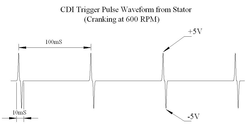
Note the peak signal of plus/minus 5 volts. You'd need a lot of turns to produce this kind of voltage in the pickup coil, and it's small volume necessitates using very fine wire. That suggest the resistance should be much, much higher. There is a conflict here. Please redo the voltage and resistance tests on the trigger again and see if you get something different.
If your CDI doesn't get triggered (and we are seeing descrepancies in the triggere signal) the voltage at the CDI output with the ignition coil hooked up would read zero volts (or at least very close to zero). When the CDI gets triggered there is a very narrow moderately high voltage pulse on the CDI output which your meter may or may not capture (or it may capture part of it). Most meters will display this as randomly varying voltages as you crank the starter.
Again, measuring the CDI output with the coil disconnected is completely meaningless. Here's why:
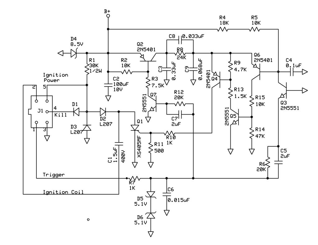
In the above schematic the AC ignition power comes in on pin 5 of the connector, is rectified by D2 and charges up C1 (the main storage capacitor - the "C" in the acronym "CDI"). But the other side of C1 must be grounded in order to get charged up. That is done through the very low resistance of the ignition coil primary (0.7 ohms or so). That is why the ignition coil must be connected fro the CDI to work. Without that connection C1 wont charge and the CDI output will only see the half wave rectified AC ignition power - which 27 volts AC sounds reasonable - but also not relevant to your problem. The above schematic is only one of many possible designs. Other CDI's may measure differently. But all CDIs need to have the coil hooked up to function.
All 5 pin CDI's as shown previously are AC powered. 4 Pin CDI's are always DC powered. The 6 pin CDI's are sometimes DC powered and sometimes AC powered. You cannot reliably tell by looking at them.
So in addition to checking your trigger pin measurements again, Look at the color of the trigger pin wire at the CDI connector. Find the same color wire in the harness down at the stator connector (which is where the trigger signal comes from). Disconnect the stator connector(s) and measure the trigger wire resistance looking into the stator to ground. Do you still see 4.52 ohms here?
You also measured 0.18 volts for the trigger signal while cranking the starter. That seems almost in the proper range. This conflicts with the 4.52 ohms though. The waveform coming out of the trigger pickup coil looks like this when measured with an oscilloscope:
Note the peak signal of plus/minus 5 volts. You'd need a lot of turns to produce this kind of voltage in the pickup coil, and it's small volume necessitates using very fine wire. That suggest the resistance should be much, much higher. There is a conflict here. Please redo the voltage and resistance tests on the trigger again and see if you get something different.
If your CDI doesn't get triggered (and we are seeing descrepancies in the triggere signal) the voltage at the CDI output with the ignition coil hooked up would read zero volts (or at least very close to zero). When the CDI gets triggered there is a very narrow moderately high voltage pulse on the CDI output which your meter may or may not capture (or it may capture part of it). Most meters will display this as randomly varying voltages as you crank the starter.
Again, measuring the CDI output with the coil disconnected is completely meaningless. Here's why:
In the above schematic the AC ignition power comes in on pin 5 of the connector, is rectified by D2 and charges up C1 (the main storage capacitor - the "C" in the acronym "CDI"). But the other side of C1 must be grounded in order to get charged up. That is done through the very low resistance of the ignition coil primary (0.7 ohms or so). That is why the ignition coil must be connected fro the CDI to work. Without that connection C1 wont charge and the CDI output will only see the half wave rectified AC ignition power - which 27 volts AC sounds reasonable - but also not relevant to your problem. The above schematic is only one of many possible designs. Other CDI's may measure differently. But all CDIs need to have the coil hooked up to function.
All 5 pin CDI's as shown previously are AC powered. 4 Pin CDI's are always DC powered. The 6 pin CDI's are sometimes DC powered and sometimes AC powered. You cannot reliably tell by looking at them.
So in addition to checking your trigger pin measurements again, Look at the color of the trigger pin wire at the CDI connector. Find the same color wire in the harness down at the stator connector (which is where the trigger signal comes from). Disconnect the stator connector(s) and measure the trigger wire resistance looking into the stator to ground. Do you still see 4.52 ohms here?