
Tao 110 no spark w/5 wire CDI
 Oct 6, 2012 | 01:43 PM
#1

Thread Starter
|
Weekend Warrior
Joined: Oct 2012
Posts: 3
Likes: 0
Need some help in a no fire issue. I have ran threw all the tests in another post. And have found that i have no AC volts at the connector at the CDI. Im leaning towards a bad stator but am unable to find a diagram nor info as to properly test the entire stator. 5 wire by the way.
Thanks in advance.
PS. any other suggestions greatly appreciated.
Thanks in advance.
PS. any other suggestions greatly appreciated.
Oct 7, 2012 | 12:21 AM
#2

Electrical Expert
Likes High Voltage In The Tub!
Likes High Voltage In The Tub!
Joined: Dec 2008
Posts: 3,260
Likes: 14
From: Tracy, California, USA
Just to cover all bases, could I get a complete list of your test results for each of the tests please? Sometimes there is valuable data in those readings that may not be readilly obvious to you.
You have no AC ignition power voltage. But what about the resistance tests for this same signal line? Is it open, or shorted? That's valuable info. The tests which you refer to determine that, and I have no data to work with in that regard.
If you don't have ignition power at the CDI connector, then the next step is to move down to the stator area, and measure voltages and resistances there.
Here is the 5 pin CDI no spark generic procedure again:
Is this a picture of your CDI?
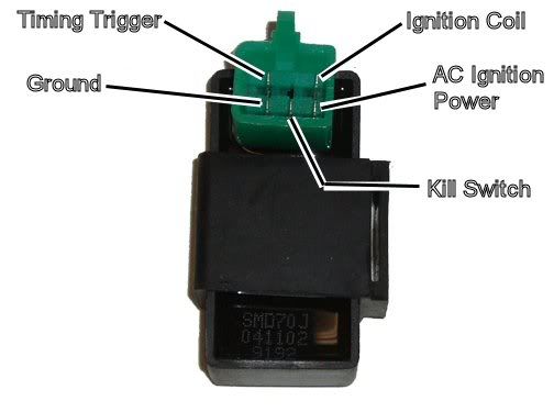
Assuming the answer is yes, the first thing to do is eliminate all kill switches and kill switch wiring:
Method 1) Unplug the CDI and remove the kill switch pin in the CDI connector on the wiring harness. The pin is held in with a spring tab on the pin itself. You'll have to probe into the connector and push this tab in order to extract the pin. Plug the CDI back in (kill switch wire dangling) and see if you have spark.
Method 2) Unplug the CDI. Turn on the ignition switch and set all kill switches to the run position. Use a meter to measure resistance in of the kill switch pin in the wiring harness connector to engine/frame ground. If the reistance is infinite on the 100K ohm scale then your kill switches/kill switch wiring are OK. If you measure zero ohms then you have a kill switch/wiring issue.
The other inputs your CDI needs to make spark are AC Ignition Power, and the Trigger signal. Do the following:
1) Unplug the CDI. In the wiring connector measure the resistance of the AC Ignition Power pin to the Ground pin. You should see 400 ohms or so. What do you measure?
2) Measure the resistance of the Timing/trigger pin to the ground pin. You should measure 150 ohms or so. What do you measure?
3) Leave the CDI unplugged. Set your meter to measure AC volts on the 100 volt scale. Measure the voltage on the AC Ignition Power pin to the ground pin while cranking the engine. You should see 40 to 80 volts AC while the engine is cranking. What do you measure?
4) Set your meter to measure AC volts on the lowest scale you have. Ideally this would be 2 volts but many meters don't go down this low. In that case use the lowest scale you have. Measure the voltage on the Timing Trigger pin to the Ground pin while cranking the engine. You should 0.2 t0 0.4 volts AC. What do you measure?
Now for measuring the output side of the CDI:
A) Leave the CDI unplugged. In the CDI wiring connector measure the resistance of the Ignition Coil pin to the ground pin. You should measure less than 1 ohm (but not zero ohms). What do you measure?
B) Plug the CDI back in. Set your meter to measure AC volts on the 20 volt scale. Set all kill switches to the run position. Crank the engine while measuring the voltage on the Igntition Coil pin to ground. Poke through the insulation of the wire if you can't probe the connector.
Caution: There should be moderately high voltage spikes on this wire. Make sure your fingers are not part of the circuitry. Don't touch the probe lead tips while doing this test.
What you should see is a lot of random numbers with lots of zero values as well. This is because the meter may catch all or part of the spark event voltage, with a lot of nothing in between. Describe what you see.
Note: Using a meter to measure this point produces highly variable results depending on the meter. What you really need is an oscilloscope, but most always a meter is all that is available. We have to do the best we can with what's available. Describe the meter results as accurately as you can - there is information there to chew on....
Oct 7, 2012 | 09:42 PM
#4
Electrical Expert
Likes High Voltage In The Tub!
Likes High Voltage In The Tub!
Joined: Dec 2008
Posts: 3,260
Likes: 14
From: Tracy, California, USA
Excellent. The complete data set is helpful to me since the several of the test overlap, and should corroborate (but sometimes conflict) with each other. Measurement error is very common, and the cross checking between tests help me judge the veracity of the data.
You data corroborates perfectly, and I agree with your original diagnosis - you have no AC ignition power from the stator.
Look at the wire color in your harness attached to the AC ignition power pin of the CDI. Usually it is black/red, but there is no gaurantee of that. Next go down to the stator where the stator wires come out of the engine. Follow those wire to the wiring harness connector sets(). Find the same wire AC Ignition power identified above (again usually black/red) on the harness side of the connector. Check this connection carefully for bad contacts, then unplug this connector and measure the resistance of the AC Ignitin Power wire going into the stator to frame ground (or the negative battery terminal). Do you see 450 ohms or so, or is it still open?
Note that all we're doing is moving down the chain. Test 1) above measured the resistance of the AC ignition power winding in the stator through the wiring harness, Now we're just doing the same thing at the stator itself.
If you find it open at the stator then the problem is in the stator, and if you find it reading fine here then the wiring between the stator and the CDI is open. Divide and conquer....
If your problem is inside the stator I would open of the engine and get at the stator for a look see before buying a new stator. You may just find a broken wire connection which can be fixed. Just keep in mind that the stator is a high vibration and high temperature environment, so you can't just fix things with electrical tape. Solder and heat shrinkable tubing is OK, as is non-corrosive Room Temperature Vulcanizing (RTV) silicone rubber such as Dow Corning 3145. Silicone rubber such as bathtub caulking is unacceptable since it cures by exuding acetic acid (a vinegar smell from the tube is a dead giveaway).
Oct 8, 2012 | 10:46 AM
#5
Thread Starter
|
Weekend Warrior
Joined: Oct 2012
Posts: 3
Likes: 0
Ok. so I pulled the cover off to take a look at the windings inside and low and behold the AC coil is open. And I cannot seem to find the break and appears to have a good solder connection at both ends. I believe this "is" the issue!
Ordered and ill update when it arrives to let you know the outcome
Ordered and ill update when it arrives to let you know the outcome
Nov 8, 2020 | 10:05 PM
#6

Weekend Warrior
Joined: Nov 2020
Posts: 1
Likes: 0
Ok. so I pulled the cover off to take a look at the windings inside and low and behold the AC coil is open. And I cannot seem to find the break and appears to have a good solder connection at both ends. I believe this "is" the issue!
Ordered and ill update when it arrives to let you know the outcome
Ordered and ill update when it arrives to let you know the outcome

Thread
Thread Starter
Forum
Replies
Last Post
Currently Active Users Viewing This Thread: 1 (0 members and 1 guests)