
No spark
 Oct 16, 2012 | 11:38 PM
#2

Electrical Expert
Likes High Voltage In The Tub!
Likes High Voltage In The Tub!
Joined: Dec 2008
Posts: 3,260
Likes: 14
From: Tracy, California, USA
4 stroke? 2 stroke?
How many pins on your CDI? Five, Four? Six (on two connectors)?
What is the history of this quad (whoops buggy )? Have you ever seen it run?
How many pins on your CDI? Five, Four? Six (on two connectors)?
What is the history of this quad (whoops buggy
)? Have you ever seen it run?
Oct 17, 2012 | 03:47 PM
#3

Thread Starter
|
Weekend Warrior
Joined: Oct 2012
Posts: 5
Likes: 0
Lynn,
thanks for your reply. it was given to my son in a non running condition. as stated there is no spark. here are some of the measurements I checked.
stator: 48vac and 302ohms to ground
trigger:0.3vac and 131ohms to ground
no output voltage from CDI to coil. black/yellow wire from CDI to coil 1ohm.
its a 5 pin AC Chinese CDI. removed white/black kill wire from connector and have good ground on green wire. 48vac on black/red wire and 0.3vac on blue/yellow wire.
someone cut off the CDI connector on the main harness and I'm not sure which wire goes to the pins on the CDI! I did find a pin out for the 5 pin CDI box online.if the CDI box is laying flat and the connector and clip are to the left there are 2 columns of 3 pins.starting top left column and going down
1-black/yellow,to coil
2-blank no pin
3-yellow/blue,from trigger
top right column going down
4-black/red,AC Ignition power
5-white/black,motor kill
6-green,ground.
I order a new CDI box and main harness,but the new harness connector for the CDI box is (looking down on the harness as its plugged into the CDI box
1-black/yellow
2-blank
3-yellow/blue
4-white/black
5-black/red
6-green
the black/red and white/black are in different slots.which is correct? could the factory harness be wired wrong? is the pin out I found online correct? all the post I have read the white/black kill wire is in the middle pin on the right side of the column. I don't want to burn up the CDI box.
thanks for your help!
Oct 17, 2012 | 11:26 PM
#4
Electrical Expert
Likes High Voltage In The Tub!
Likes High Voltage In The Tub!
Joined: Dec 2008
Posts: 3,260
Likes: 14
From: Tracy, California, USA
Here's the way a five pin CDI is wired:
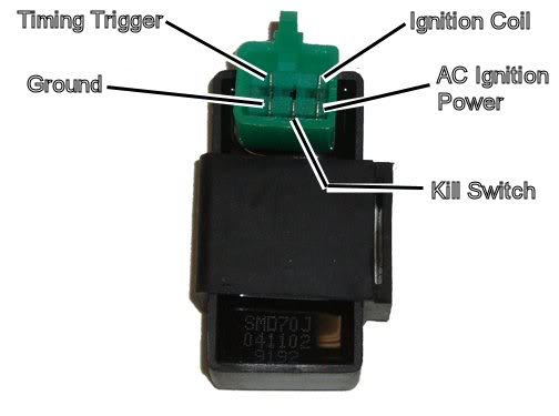
So it looks to me like your new harness is wrong.
I doubt reversing those two wires will burn out the CDI. The kill switch (miswired per your harness connections) would only apply zero volts to the power connection (no biggee there), and apply 48 volts AC to the trigger input. That is a high impedance input, and protected. Every internal CDI schematic that I've seen suggests that this is no biggee either.
But of course the CDI won't work if you get the two wires reversed....
From your troubleshooting data all the indicators are pointing to your CDI as being bad. You've got power and ground to the CDI, you've got a trigger signal, and yet no signal to the ignition coil - which also measures in the ballpark for input resistance - so it's not shorted. If it were me I'd change the CDI and then see where we are at. If that doesn't work we'll look deeper...
Lynn,
thanks for your reply. it was given to my son in a non running condition. as stated there is no spark. here are some of the measurements I checked.
stator: 48vac and 302ohms to ground
trigger:0.3vac and 131ohms to ground
no output voltage from CDI to coil. black/yellow wire from CDI to coil 1ohm.
its a 5 pin AC Chinese CDI. removed white/black kill wire from connector and have good ground on green wire. 48vac on black/red wire and 0.3vac on blue/yellow wire.
someone cut off the CDI connector on the main harness and I'm not sure which wire goes to the pins on the CDI! I did find a pin out for the 5 pin CDI box online.if the CDI box is laying flat and the connector and clip are to the left there are 2 columns of 3 pins.starting top left column and going down
1-black/yellow,to coil
2-blank no pin
3-yellow/blue,from trigger
top right column going down
4-black/red,AC Ignition power
5-white/black,motor kill
6-green,ground.
I order a new CDI box and main harness,but the new harness connector for the CDI box is (looking down on the harness as its plugged into the CDI box
1-black/yellow
2-blank
3-yellow/blue
4-white/black
5-black/red
6-green
the black/red and white/black are in different slots.which is correct? could the factory harness be wired wrong? is the pin out I found online correct? all the post I have read the white/black kill wire is in the middle pin on the right side of the column. I don't want to burn up the CDI box.
thanks for your help!
thanks for your reply. it was given to my son in a non running condition. as stated there is no spark. here are some of the measurements I checked.
stator: 48vac and 302ohms to ground
trigger:0.3vac and 131ohms to ground
no output voltage from CDI to coil. black/yellow wire from CDI to coil 1ohm.
its a 5 pin AC Chinese CDI. removed white/black kill wire from connector and have good ground on green wire. 48vac on black/red wire and 0.3vac on blue/yellow wire.
someone cut off the CDI connector on the main harness and I'm not sure which wire goes to the pins on the CDI! I did find a pin out for the 5 pin CDI box online.if the CDI box is laying flat and the connector and clip are to the left there are 2 columns of 3 pins.starting top left column and going down
1-black/yellow,to coil
2-blank no pin
3-yellow/blue,from trigger
top right column going down
4-black/red,AC Ignition power
5-white/black,motor kill
6-green,ground.
I order a new CDI box and main harness,but the new harness connector for the CDI box is (looking down on the harness as its plugged into the CDI box
1-black/yellow
2-blank
3-yellow/blue
4-white/black
5-black/red
6-green
the black/red and white/black are in different slots.which is correct? could the factory harness be wired wrong? is the pin out I found online correct? all the post I have read the white/black kill wire is in the middle pin on the right side of the column. I don't want to burn up the CDI box.
thanks for your help!
Oct 19, 2012 | 12:10 AM
#6
Electrical Expert
Likes High Voltage In The Tub!
Likes High Voltage In The Tub!
Joined: Dec 2008
Posts: 3,260
Likes: 14
From: Tracy, California, USA
It's time to recheck your measurements from before with the new CDI, and again with the old CDI.
Remember that your measurements said that you have:
1) A good ground at the the CDI,
2) The AC power voltage to the CDI was good
3) The resistance of the AC power winding was believable
4) The Trigger voltage was in the range
5) The trigger winding resistance was OK
So according to your measurements the inputs to the CDI are good, and there is no voltage output.
Let's weigh the possibilities:
A) You didn't do the measurements right and are fooling yourself - A very common problem, even for an experienced person like me. Troubleshooting problems is always a three steps forward, and two back - to make sure you always get the same results when you repeat them.
B) The first CDI is bad, and so is the second one. It can happen. Where did you get this second CDI?
C) The ignition coil has a shorted turn (or turns). This would bring the inductance of the ignition coil to zero, and prevent any CDI output voltage from showing up.
D) The two CDIs aren't getting triggered. This conflicts with your 0.3 VAC cranking voltage. Are you sure you got (and still get) 0.3 VAC while cranking? And (equally important to eliminate a bad meter with an offset) do you read 0.0 volts when the engine isn't cranking?
Trending Topics


Thread
Thread Starter
Forum
Replies
Last Post
fordfaithful21
Polaris Ask an Expert! In fond memory of Old Polaris Tech.
9
Dec 7, 2015 05:52 PM
Cdenton
Technical and How-To Articles
1
Sep 9, 2015 11:23 AM
Currently Active Users Viewing This Thread: 1 (0 members and 1 guests)