
yamota 150cc atv
 Dec 16, 2012 | 03:38 PM
#11

Thread Starter
|
Weekend Warrior
Joined: Dec 2012
Posts: 9
Likes: 0
From: norway,bergen,
seems that my brake light is one all the time because i connected tow wire together in the front that i think is for natural light? i am missing some part her?
when i connect a 5w light bulb there the brake light turns off and the engine wont turn/crank someone that no what i am missing ?
its a tow pin connector wire is green and yellow and the other is black
when i connect a 5w light bulb there the brake light turns off and the engine wont turn/crank someone that no what i am missing ?
its a tow pin connector wire is green and yellow and the other is black
Dec 16, 2012 | 09:57 PM
#12

Electrical Expert
Likes High Voltage In The Tub!
Likes High Voltage In The Tub!
Joined: Dec 2008
Posts: 3,260
Likes: 14
From: Tracy, California, USA
Hey , i have 6 pin on cdi yes 4 in one and 2 in the other,but just one wire in the 2pin connector it don't have the kill switch wire
the ignition power on cdi i have ,i just a light bulb h7 12v 55w and a meter
on the whit color wire in to stator i get slowly week light when cranking engine ,the ground is ok allover,the engine turns inn all 3 positions of the run/kill switch. i put some new pic in the albums,
tanks for helping
the ignition power on cdi i have ,i just a light bulb h7 12v 55w and a meter
on the whit color wire in to stator i get slowly week light when cranking engine ,the ground is ok allover,the engine turns inn all 3 positions of the run/kill switch. i put some new pic in the albums,
tanks for helping
It is time to switch to your meter.
Here is a generic procedure for testing DC power 6 pin CDI ignition systems:
To troubleshoot no spark problems on a 6 pin DC powered CDI it makes sense to start in the middle (the CDI), measure as much as we can and branch out from there. For the CDI to do its thing it needs power, a trigger pulse, and it must not be inhibited via the kill switch input pin.
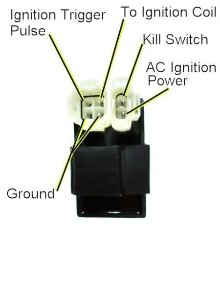
1) Unplug the CDI. Turn the ignition switch on. Set all kill switches the the "run" position. In the wiring harness, look to see if you have a wire on the kill switch pin. If you do, measure the resistance of the kill switch pin to the ground pin on the 20K ohm scale. It should read infinite ohms (same as when the meter leads are hanging free and not touching anything). It should not read zero ohms (shorted).
2) Leave the CDI unplugged, and the ignition switch in the "on" position. Use a meter to measure the DC voltage on the pin labeled "AC ignition power" in the wiring harness to the ground wire on the 2K ohm scale. You should read battery voltage (12 volts). What do you measure?
3) Leave the CDI unplugged. Use a meter to measure the resistance of the "Ignition Trigger Pulse" pin in the wiring harness to the ground wire on the 2K ohm scale. You should read approximately 150 ohms. What do you measure?
4) Set your meter down to the lowest scale you have for measuring AC volts. 2 volts would be ideal, but some meters don't go that low. In that case use the lowest scale you have. While cranking the engine, measure the voltage on the Ignition Trigger Pulse pin in the wiring harness to the ground pin. You should measure 0.2 to 0.5 volts AC. What do you measure?
5) Now plug the CDI back in. Measure the AC voltage on the Ignition Coil pin to the ground pin using the 200 volt scale. If you have to, use a sewing pin to poke through the wire insulation and then put the meter probe on the sewing pin. But don't hold your fingers on the connection during the next test - there may be high voltage here when the engine is turning. With the ignition on and all kill switches set to the "run" position, crank the starter motor. You should see voltages bouncing around at random values and the meter captures all or part of a spark event. What do you see?
Dec 16, 2012 | 10:12 PM
#13
Electrical Expert
Likes High Voltage In The Tub!
Likes High Voltage In The Tub!
Joined: Dec 2008
Posts: 3,260
Likes: 14
From: Tracy, California, USA
What?
You hooked your neutral and brake light switches together?
Why would you do this? It makes no sense. These two systems have absolutely nothing to do with each other. Randomly hooking these or other unrelated systems together can wreck stuff. Then you still have the original problem, *plus* all the new ones you have self inflicted upon yourself .
.
Don't do random wiring guess work. It *always* leads to trouble. Follow the procedure using a meter. Do accurate measurements, and make sure they are repeatable before posting back the results.
You hooked your neutral and brake light switches together?
Why would you do this? It makes no sense. These two systems have absolutely nothing to do with each other. Randomly hooking these or other unrelated systems together can wreck stuff. Then you still have the original problem, *plus* all the new ones you have self inflicted upon yourself
.Don't do random wiring guess work. It *always* leads to trouble. Follow the procedure using a meter.
Do accurate measurements, and make sure they are repeatable before posting back the results.seems that my brake light is one all the time because i connected tow wire together in the front that i think is for natural light? i am missing some part her?
when i connect a 5w light bulb there the brake light turns off and the engine wont turn/crank someone that no what i am missing ?
its a tow pin connector wire is green and yellow and the other is black
when i connect a 5w light bulb there the brake light turns off and the engine wont turn/crank someone that no what i am missing ?
its a tow pin connector wire is green and yellow and the other is black
Dec 17, 2012 | 12:46 PM
#14
Thread Starter
|
Weekend Warrior
Joined: Dec 2012
Posts: 9
Likes: 0
From: norway,bergen,
What?
You hooked your neutral and brake light switches together?
Why would you do this? It makes no sense. These two systems have absolutely nothing to do with each other. Randomly hooking these or other unrelated systems together can wreck stuff. Then you still have the original problem, *plus* all the new ones you have self inflicted upon yourself.
Don't do random wiring guess work. It *always* leads to trouble. Follow the procedure using a meter. Do accurate measurements, and make sure they are repeatable before posting back the results.
You hooked your neutral and brake light switches together?
Why would you do this? It makes no sense. These two systems have absolutely nothing to do with each other. Randomly hooking these or other unrelated systems together can wreck stuff. Then you still have the original problem, *plus* all the new ones you have self inflicted upon yourself
.Don't do random wiring guess work. It *always* leads to trouble. Follow the procedure using a meter.
Do accurate measurements, and make sure they are repeatable before posting back the results.the tow wires i connected together i think is for natural light on the top of steering bar , aim missing something for this tow wires
Dec 18, 2012 | 12:01 AM
#15
Electrical Expert
Likes High Voltage In The Tub!
Likes High Voltage In The Tub!
Joined: Dec 2008
Posts: 3,260
Likes: 14
From: Tracy, California, USA
Ok. I think I was not understanding you completely, but we'll figure it out as we proceed .
Re: Neutral switches/lights and brake switches:
By "natural light" I'm assuming you mean "neutral light", a light that illuminates when the quad is in neutral (engine not connected by gears to the wheels). But that is different from a "neutral switch" which is activated mechanically and applies a ground to the "neutral light" lighting it up.
What type of brakes do you have? Front brakes are right handlebar lever activated, correct? Are the rear brakes activated by the left handle lever, or are they activated with a right foot pedal?
I would find it very strange to have a quad that has no brake switches. Almost all chinese quads use the brake switch in the starter motor interlock circuitry that prevents the quad starter motor from turning unless the brakes are applied. It is the same sort of safety mechanism on cars, where you cannot crank the starter motor when the car is in drive or reverse. It is a different implementation, but the same idea where you cannot start up the quad unless it is in a condition where it won't take off unexpectedly.
The above discussion about neutral and brake switches, and how they can prevent starters from cranking, has nothing to do with getting spark. If your starter motor is turning when you push the start button, brakes and neutral switches/lights are irrelevant as far as spark goes.
Spark Problems:
Ignition systems aren't like things that run off 12 volts DC. If you're looking to see if "power" gets to a 12 volt device you can use a test light (or a meter) to see if power gets there. But on an ignition system there is often *nothing* that runs on 12 volts, and *nothing* that can be tested with a light bulb. In your case it looks light you have a DC powered CDI (most still are AC powered), so it looks like maybe you could test power into the CDI but that's it.
You need a meter, and you need to follow the procedure posted previously and post the results. This is the minimum level of testing. Some of the signals are very small, and some huge, but very infrequent on average (and current limited). You can't look at this with a light bulb.
A better test plan would be to use an oscilloscope, but that is out of the reach of most quad owners. So we're stuck with a meter, and it's limited capability. We do the best with that data, but test lights? Not a chance...
. Re: Neutral switches/lights and brake switches:
By "natural light" I'm assuming you mean "neutral light", a light that illuminates when the quad is in neutral (engine not connected by gears to the wheels). But that is different from a "neutral switch" which is activated mechanically and applies a ground to the "neutral light" lighting it up.
What type of brakes do you have? Front brakes are right handlebar lever activated, correct? Are the rear brakes activated by the left handle lever, or are they activated with a right foot pedal?
I would find it very strange to have a quad that has no brake switches. Almost all chinese quads use the brake switch in the starter motor interlock circuitry that prevents the quad starter motor from turning unless the brakes are applied. It is the same sort of safety mechanism on cars, where you cannot crank the starter motor when the car is in drive or reverse. It is a different implementation, but the same idea where you cannot start up the quad unless it is in a condition where it won't take off unexpectedly.
The above discussion about neutral and brake switches, and how they can prevent starters from cranking, has nothing to do with getting spark. If your starter motor is turning when you push the start button, brakes and neutral switches/lights are irrelevant as far as spark goes.
Spark Problems:
Ignition systems aren't like things that run off 12 volts DC. If you're looking to see if "power" gets to a 12 volt device you can use a test light (or a meter) to see if power gets there. But on an ignition system there is often *nothing* that runs on 12 volts, and *nothing* that can be tested with a light bulb. In your case it looks light you have a DC powered CDI (most still are AC powered), so it looks like maybe you could test power into the CDI but that's it.
You need a meter, and you need to follow the procedure posted previously and post the results. This is the minimum level of testing. Some of the signals are very small, and some huge, but very infrequent on average (and current limited). You can't look at this with a light bulb.
A better test plan would be to use an oscilloscope, but that is out of the reach of most quad owners. So we're stuck with a meter, and it's limited capability. We do the best with that data, but test lights? Not a chance...
Feb 7, 2013 | 03:28 PM
#16
Thread Starter
|
Weekend Warrior
Joined: Dec 2012
Posts: 9
Likes: 0
From: norway,bergen,
Hello, still having problem whit this atv, still no spark???
i have now new cdi, coil ,spark plugg , key ignition switch ,stator(ignition system) , i have just left the starter switch and the regulator thats is old parts
some ides were the problem can be ???? i dont understand this
i have now new cdi, coil ,spark plugg , key ignition switch ,stator(ignition system) , i have just left the starter switch and the regulator thats is old parts
some ides were the problem can be ???? i dont understand this
Feb 8, 2013 | 02:33 PM
#17
Thread Starter
|
Weekend Warrior
Joined: Dec 2012
Posts: 9
Likes: 0
From: norway,bergen,
Hello, still having problem whit this atv, still no spark???
i have now new cdi, coil ,spark plugg , key ignition switch ,stator(ignition system) , i have just left the starter switch and the regulator thats is old parts
some ides were the problem can be ???? i dont understand this
i have now new cdi, coil ,spark plugg , key ignition switch ,stator(ignition system) , i have just left the starter switch and the regulator thats is old parts
some ides were the problem can be ???? i dont understand this
on the one standing trigger puls i have ground on.
the 2 wires standing ground i have ground ,
one the wire to coil i don't have nothing
i have power in to coil
???????
Feb 8, 2013 | 09:36 PM
#18
Electrical Expert
Likes High Voltage In The Tub!
Likes High Voltage In The Tub!
Joined: Dec 2008
Posts: 3,260
Likes: 14
From: Tracy, California, USA
If you have a meter and just need help in using it I can perhaps be of assistance. What kind of meter are you using? What is the brand and model number? I will try to look up the manual so I can follow along with you to get the leads placed correctly, and use the correct meter settings.
If your just being stubborn and insisting on using a test light, then I wish you the best of luck. I won't waste any more of my time...
Feb 9, 2013 | 03:14 PM
#19
Thread Starter
|
Weekend Warrior
Joined: Dec 2012
Posts: 9
Likes: 0
From: norway,bergen,
The procedure calls for resistance measurements in "ohms", and voltage measurements in "volts" using a meter. Do you have a meter? Or are you still insisting on using a worthless test light?
If you have a meter and just need help in using it I can perhaps be of assistance. What kind of meter are you using? What is the brand and model number? I will try to look up the manual so I can follow along with you to get the leads placed correctly, and use the correct meter settings.
If your just being stubborn and insisting on using a test light, then I wish you the best of luck. I won't waste any more of my time...
and der i have 12v on the ignition pin in, i have ground on the 2 wires,
iam all sow measuring ground on the trigger puls, and i dont have noting on the one to coil. i tink i have som problem around this , i tink i should have 12v in one the trigger puls and 12v out too coil ?? ore am i wrong
i dont have any wire on the kill switch pin on cdi
tanks for helping and i am sorry for my bad English writing .
i am jusin this meter
http://biltema.no/no/Bil---MC/Verkto...ter-bil-15292/
Feb 9, 2013 | 03:32 PM
#20
Thread Starter
|
Weekend Warrior
Joined: Dec 2012
Posts: 9
Likes: 0
From: norway,bergen,
http://forums.atvconnection.com/albu...0&ref=gnr-prev
i am missing some part her , i have a 2 wire connector in the front that is not contacted because i am missing some ting one it.
i have connected them together whit a fuse, and when i connected this wire together i get taillights/brakeligths on and i can crank the engine , when this is not connected together i cant crank engine , do you understand me and now witch part that i am missing??