
yamota 150cc atv
 Feb 10, 2013 | 08:08 PM
#21

Electrical Expert
Likes High Voltage In The Tub!
Likes High Voltage In The Tub!
Joined: Dec 2008
Posts: 3,260
Likes: 14
From: Tracy, California, USA
I tried answering this last night, but was having problems with a slow Internet Service Provider. I got one post in but then gave up after that.
Your meter looks fine. I cannot see from the picture the actual switch positions, but from the specifications everything seems OK.
So when the procedure asks you to measure resistance your meter is able to do that. And you should be able to report the results in ohms. It looks like your meter is autoranging too which is good. It will choose the best scale to give the most accurate reading. Measuring "ground" on the trigger pin is not good enough. I need more information... .
.
When you say you have 'nothing' on the wire to the ignition coil, what do you mean exactly? There are two separate measurements called for on this wire. One asks for resistance to ground in ohms, and one asks for AC voltage in volts. "Nothing" is too ambiguous. What were you measuring? Volts or ohms? And what did your meter say? Zero ohms? Infinite ohms (the same reading you get when the meters leads are hanging free and not touching anything)? Or is it zero volts (while cranking)?
No, you will not have 12 volts to the trigger coil. Nor will you have 12 volts to the ignition coil. Both of these voltages are complex and really should be measured with an oscilloscope, but in the real world these aren't always available. So we do the best we can with a meter....
Here is what those two voltages would look like on an oscilloscope (just so you can get an idea of what I'm talking about). Meters are usually used to measuresteady or unchanging voltages. An oscilloscope is just a fancy voltmeter that can measure changing / fast moving voltages and plot them on a graph display. Voltage is on the vertical axis, and time is on the horizontal axis.
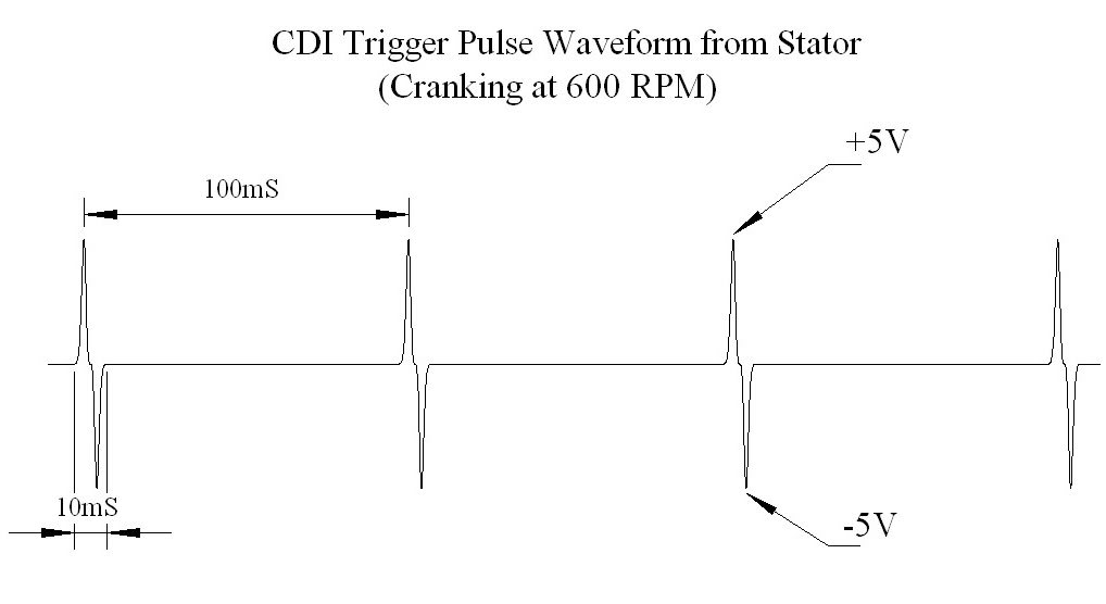
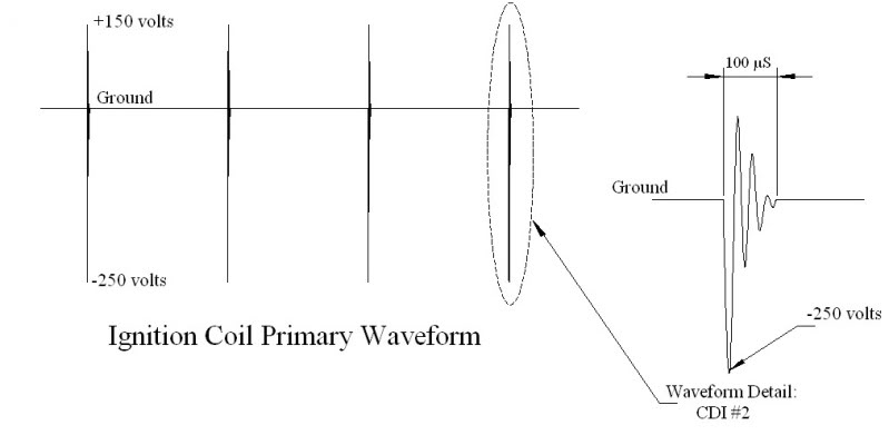
Notice how there is nothing even close to 12 volts in these pictures. Again, meters are not the proper tool for measuring these waveforms but they are the best tool that most people have. So we do the best we can with what limited tools we have.
I am able to understand you fine... .
.
hey. i have a meter yes and i have cheek t, i am measuring on my cdi
and der i have 12v on the ignition pin in, i have ground on the 2 wires,
iam all sow ....
...i am jusin this meter
Digitalt multimeter, bil - Biltema
and der i have 12v on the ignition pin in, i have ground on the 2 wires,
iam all sow ....
...i am jusin this meter
Digitalt multimeter, bil - Biltema
So when the procedure asks you to measure resistance your meter is able to do that. And you should be able to report the results in ohms. It looks like your meter is autoranging too which is good. It will choose the best scale to give the most accurate reading. Measuring "ground" on the trigger pin is not good enough. I need more information...
.No, you will not have 12 volts to the trigger coil. Nor will you have 12 volts to the ignition coil. Both of these voltages are complex and really should be measured with an oscilloscope, but in the real world these aren't always available. So we do the best we can with a meter....
Here is what those two voltages would look like on an oscilloscope (just so you can get an idea of what I'm talking about). Meters are usually used to measuresteady or unchanging voltages. An oscilloscope is just a fancy voltmeter that can measure changing / fast moving voltages and plot them on a graph display. Voltage is on the vertical axis, and time is on the horizontal axis.
Notice how there is nothing even close to 12 volts in these pictures. Again, meters are not the proper tool for measuring these waveforms but they are the best tool that most people have. So we do the best we can with what limited tools we have.
I am able to understand you fine...
.

Thread
Thread Starter
Forum
Replies
Last Post
RacewayATV
Chinese Quads
77
Oct 23, 2005 06:07 PM
Currently Active Users Viewing This Thread: 1 (0 members and 1 guests)