


TaoTao No spark
 Jun 24, 2015 | 11:15 PM
#21

Electrical Expert
Likes High Voltage In The Tub!
Likes High Voltage In The Tub!
Joined: Dec 2008
Posts: 3,260
Likes: 14
From: Tracy, California, USA

Oh my god, no!!!

If you get spark you'll be putting tens of thousands of volts into your meter!!! A well designed meter will try to mitigate "stupid engineer tricks" like this by design, but 30,000 volts is asking a lot...
I have a lot of experience with electronics, and you know the saying: "familiarity breeds contempt". I was trying to fix an electronic rat killer and wanted to measure the high voltage output. It was only 8000 volts, and my meter was rated for 2000 volts max. It was an expensive meter, and I didn't think a four to one overload was that big a deal for a quick measurement. I measured the 8000 volts, it over scaled the meter briefly, then went dead. I was able to salvage the battery and the leads - the rest of the meter went into the trash.

 Jun 24, 2015 | 11:36 PM
#23
Electrical Expert
Likes High Voltage In The Tub!
Likes High Voltage In The Tub!
Joined: Dec 2008
Posts: 3,260
Likes: 14
From: Tracy, California, USA
I agree with Jaster94 in that your original problem was most likely a bad wire connection somewhere. But now you've complicated the issue by blindly changing a lot of parts. What is one of those parts were bad, or maybe just a wrong part for your quad? Now you might have two problems (or even more). That could make things a lot harder...
Below is a generic procedure for troubleshooting no spark for a 5 pin AC powered CDI. You've already eliminated the kill switch input part, so carry on from that step and let me know what you measure.
Please tell me what meter you are using. I need brand and model number. I will try to look up spec's on that meter so I can follow along with your tests. And could you please tell me what setting/scale you set your meter to for all the tests at each step.
Finally, please don't tell me your interpretations of what the meter is telling you. Tell me exactly what the meter display says in as much detail as you can (as well as the setting/scale you are using). Two of the most common (and completely useless) comments I get back for measurement results are:
1) "I got nothing"
2) "It all measured good"
Please avoid those kinds of generalities...

Is this a picture of your CDI?
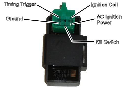
Assuming the answer is yes, the first thing to do is eliminate all kill switches and kill switch wiring:
Method 1) Unplug the CDI and remove the kill switch pin in the CDI connector on the wiring harness. The pin is held in with a spring tab on the pin itself. You'll have to probe into the connector and push this tab in order to extract the pin. Plug the CDI back in (kill switch wire dangling) and see if you have spark.
Method 2) Unplug the CDI. Turn on the ignition switch and set all kill switches to the run position. Use a meter to measure resistance in of the kill switch pin in the wiring harness connector to engine/frame ground. If the resistance is infinite on the 200K ohm scale then your kill switches/kill switch wiring are OK. If you measure zero ohms then you have a kill switch/wiring issue.
The other inputs your CDI needs to make spark are AC Ignition Power, and the Trigger signal. Do the following:
1) Unplug the CDI. In the wiring connector measure the resistance of the AC Ignition Power pin to the Ground pin. You should see 400 ohms or so. What do you measure?
2) Measure the resistance of the Timing/trigger pin to the ground pin. You should measure 150 ohms or so. What do you measure?
3) Leave the CDI unplugged. Set your meter to measure AC volts on the 100 volt scale. Measure the voltage on the AC Ignition Power pin to the ground pin while cranking the engine. You should see 40 to 80 volts AC while the engine is cranking. What do you measure?
4) Set your meter to measure AC volts on the lowest scale you have. Ideally this would be 2 volts but many meters don't go down this low. In that case use the lowest scale you have. Measure the voltage on the Timing Trigger pin to the Ground pin while cranking the engine. You should 0.2 t0 0.4 volts AC. What do you measure?
Now for measuring the output side of the CDI:
A) Leave the CDI unplugged. In the CDI wiring connector measure the resistance of the Ignition Coil pin to the ground pin. You should measure less than 1 ohm (but not zero ohms). What do you measure?
B) Plug the CDI back in. Set your meter to measure AC volts on the 20 volt scale. Set all kill switches to the run position. Crank the engine while measuring the voltage on the Igntition Coil pin to ground. Poke through the insulation of the wire if you can't probe the connector.
Caution: There should be moderately high voltage spikes on this wire. Make sure your fingers are not part of the circuitry. Don't touch the probe lead tips while doing this test.
What you should see is a lot of random numbers with lots of zero values as well. This is because the meter may catch all or part of the spark event voltage, with a lot of nothing in between. Describe what you see.
Note: Using a meter to measure this point produces highly variable results depending on the meter. What you really need is an oscilloscope, but most always a meter is all that is available. We have to do the best we can with what's available. Describe the meter results as accurately as you can - there is information there to chew on....
Assuming the answer is yes, the first thing to do is eliminate all kill switches and kill switch wiring:
Method 1) Unplug the CDI and remove the kill switch pin in the CDI connector on the wiring harness. The pin is held in with a spring tab on the pin itself. You'll have to probe into the connector and push this tab in order to extract the pin. Plug the CDI back in (kill switch wire dangling) and see if you have spark.
Method 2) Unplug the CDI. Turn on the ignition switch and set all kill switches to the run position. Use a meter to measure resistance in of the kill switch pin in the wiring harness connector to engine/frame ground. If the resistance is infinite on the 200K ohm scale then your kill switches/kill switch wiring are OK. If you measure zero ohms then you have a kill switch/wiring issue.
The other inputs your CDI needs to make spark are AC Ignition Power, and the Trigger signal. Do the following:
1) Unplug the CDI. In the wiring connector measure the resistance of the AC Ignition Power pin to the Ground pin. You should see 400 ohms or so. What do you measure?
2) Measure the resistance of the Timing/trigger pin to the ground pin. You should measure 150 ohms or so. What do you measure?
3) Leave the CDI unplugged. Set your meter to measure AC volts on the 100 volt scale. Measure the voltage on the AC Ignition Power pin to the ground pin while cranking the engine. You should see 40 to 80 volts AC while the engine is cranking. What do you measure?
4) Set your meter to measure AC volts on the lowest scale you have. Ideally this would be 2 volts but many meters don't go down this low. In that case use the lowest scale you have. Measure the voltage on the Timing Trigger pin to the Ground pin while cranking the engine. You should 0.2 t0 0.4 volts AC. What do you measure?
Now for measuring the output side of the CDI:
A) Leave the CDI unplugged. In the CDI wiring connector measure the resistance of the Ignition Coil pin to the ground pin. You should measure less than 1 ohm (but not zero ohms). What do you measure?
B) Plug the CDI back in. Set your meter to measure AC volts on the 20 volt scale. Set all kill switches to the run position. Crank the engine while measuring the voltage on the Igntition Coil pin to ground. Poke through the insulation of the wire if you can't probe the connector.
Caution: There should be moderately high voltage spikes on this wire. Make sure your fingers are not part of the circuitry. Don't touch the probe lead tips while doing this test.
What you should see is a lot of random numbers with lots of zero values as well. This is because the meter may catch all or part of the spark event voltage, with a lot of nothing in between. Describe what you see.
Note: Using a meter to measure this point produces highly variable results depending on the meter. What you really need is an oscilloscope, but most always a meter is all that is available. We have to do the best we can with what's available. Describe the meter results as accurately as you can - there is information there to chew on....
 Jun 25, 2015 | 12:16 PM
#25
I agree with Jaster94 in that your original problem was most likely a bad wire connection somewhere. But now you've complicated the issue by blindly changing a lot of parts. What is one of those parts were bad, or maybe just a wrong part for your quad? Now you might have two problems (or even more). That could make things a lot harder...
Below is a generic procedure for troubleshooting no spark for a 5 pin AC powered CDI. You've already eliminated the kill switch input part, so carry on from that step and let me know what you measure.
Please tell me what meter you are using. I need brand and model number. I will try to look up spec's on that meter so I can follow along with your tests. And could you please tell me what setting/scale you set your meter to for all the tests at each step.
Finally, please don't tell me your interpretations of what the meter is telling you. Tell me exactly what the meter display says in as much detail as you can (as well as the setting/scale you are using). Two of the most common (and completely useless) comments I get back for measurement results are:
1) "I got nothing"
2) "It all measured good"
Please avoid those kinds of generalities...
Below is a generic procedure for troubleshooting no spark for a 5 pin AC powered CDI. You've already eliminated the kill switch input part, so carry on from that step and let me know what you measure.
Please tell me what meter you are using. I need brand and model number. I will try to look up spec's on that meter so I can follow along with your tests. And could you please tell me what setting/scale you set your meter to for all the tests at each step.
Finally, please don't tell me your interpretations of what the meter is telling you. Tell me exactly what the meter display says in as much detail as you can (as well as the setting/scale you are using). Two of the most common (and completely useless) comments I get back for measurement results are:
1) "I got nothing"
2) "It all measured good"
Please avoid those kinds of generalities...
I am using a Cen-tech digital multimeter. I don't see a model number on it. I bought it off ebay for next to nothing. http://www.ebay.com/itm/301069357669?_trksid=p2057872.m2749.l2649&ssPageName=STRK%3AMEBIDX%3AIT
That is the link to the meter I bought.
I don't know what the diff is between DCV 200 and 200m. Also, the DCA has 200m. Im confused.
Jun 25, 2015 | 11:09 PM
#26
Electrical Expert
Likes High Voltage In The Tub!
Likes High Voltage In The Tub!
Joined: Dec 2008
Posts: 3,260
Likes: 14
From: Tracy, California, USA
Actually Dammar, it's my bad.

You never said to measure voltage to the spark plug with a meter. You only mentioned measuring resistance. Measuring resistance is fine.
I apologize for misreading your post, and going on a rant. You did not do anything wrong. I did, by not reading carefully...
Jun 26, 2015 | 12:06 AM
#27
Electrical Expert
Likes High Voltage In The Tub!
Likes High Voltage In The Tub!
Joined: Dec 2008
Posts: 3,260
Likes: 14
From: Tracy, California, USA
I'm familiar with that meter. I have several of them. They are really lousy meters as far as reliability goes, but if you have one that works it can be a good tool.
The advantage of these meters is that they are really cheap. The disadvantage is that many of them don't work out of the box, or fail shortly after you start using them. Still, when I needed to simultaneously measure five things at once, having five of these is the cheapest way to go even though I had to buy seven of them to get five good ones.
DCV means you're measuring DC voltage measured in volts. DCA means you're measuring DC amps. These are completely different measurements and many people use them interchangeably (and wrongly).
Let's use an analogy using water pipes:
Voltage in an electrical circuit is similar to pressure in a water pipe. You need water pressure to make water move through a partially opened faucet (or whatever). But pressure alone does not tell you how much water is flowing in the pipe. Flow rate (measured in, say, gallons per minute) is similar to electrical current (measured in amps). One amp = 1 coulomb per second, and one coulomb = some giant number of electrons that nobody remembers except google.
You won't be measuring amps (current) at all in the CDI tests, so just stay away from those DCA settings. You will be measuring voltage (AC and DC), and resistance (in ohms).
The difference between 200 and 200m is huge on the DC voltage scales. Cen-tech took some shortcuts on their scale labeling. "200m" really means 200 millivolts, or 0.200 volts. "200" means 200 volts (or 200,000 millivolts. Notice how the scales on your increase from the CCW beginning to the CW end of the DC voltage scales:
200m = 200 millivolts = 0.200 volts fullscale
2000m = 2000 millivolts = 2.000 volts full scale
20 = 20,000 millivolts = 20 volts full scale
200 = 200,000 millivolts = 200 volts full scale
1000 = 1,000,000 millivolts = 1000 volts full scale
The same applies to the resistance scales, except now we have 200 ohms, then 2000 ohms, then 20 kilo Ohms (equals 20,000 ohms), then 200 kilo Ohms (equals 200,000 ohms), then 2000 kilo Ohms ( equals 2,000,000 ohms and also equals 2 mega ohms).
Jun 26, 2015 | 07:06 AM
#28
Now that is one heck of an explanation. That really helps a lot. I will do that CDI test here this morning and report back. When checking the ohms per the testing procedure, do I turn my meter to the 2000k?
I can't thank you guys enough for helping me out.
I can't thank you guys enough for helping me out.
Jun 27, 2015 | 02:10 AM
#29
Electrical Expert
Likes High Voltage In The Tub!
Likes High Voltage In The Tub!
Joined: Dec 2008
Posts: 3,260
Likes: 14
From: Tracy, California, USA
You'll have to hunt around to find the best scale to use. Let's say the resistance you are about to measure is 1524 ohms (which is also 1.524 Kilo ohms). But you don't know that yet, you are just trying to determine what the mystery resistance is. This is what you would read on the Cen-tech meter resistance scales for 1524 ohms (the "_" character indicates a blank):
2000K scale: ___1 or ___2 [kilo ohms]
200K scale: __1.5 [kilo ohms]
20K scale: _1.52 [kilo ohms]
2000 Ohm scale: 1524 [ohms]
200 ohm scale: 1___ [ohms]
Note how the 2000 ohm scale gives the answer with the highest resolution for a resistance of 1524 ohms. Also note that the 200 ohm scale reads open - i.e. the meter is pegged.
Below is some info I cut and pasted in from another post:
RE: scales... Meters are incredible devices when you think about it. For voltages and resistances they can measure over an huge range of values - and do so with just a simple switch selection. Think about measuring weight for example (which is where the term "scale" comes from). I have weight scales at work that measure in fractional grams. I have scales that measure a few kilograms. I have scales that measure hundreds of kilograms. There are truck scales out there that measure tens of thousands of kilograms. Yet each of these weight scales are stand alone devices and can measure only over a very limited range. You can't determine how much postage you need on a letter by weighing it on a truck scale. There just isn't enough resolution on a truck scale to measure down to a fractional ounces (or grams). By the same token you can't take a postage scale and drive a truck up onto it to measure the weight of the truck. You have to choose the right "scale" to do the job.
Again, a meter is an incredible tool. You can measure ohms (for example) from fractions of an ohm, to ohms, to 1000's of an ohm (K ohms), or even millions of ohms (M ohms), simply by changing a switch position. And all of this for less than $20. Imagine a weight scale that can accurately measure the weight of a fully loaded tractor trailer truck down to the weight of a grain of rice by just switching a switch, and all for just $20 or less...
So when you measure resistance you want to choose a scale that gives the most resolution possible. So you turn down the "scale" to lower and lower values until you get an over range - i.e. you get the same reading as when the leads are not touching anything. Then you go back up one scale and use that reading. Imagine putting a 10 pound sack of potatoes on a postage (weight) scale. It is going to hit the upperlimit (whatever that is) and peg the meter. Adding more weight (like another sack of potatoes) won't change anything - the meter is still pegged. You need to move the sack(s) of potatoes over to a different scale that can handle the higher weight - say a scale that can measure 50 pounds maximum. Your ohm meter is the same. When it is pegged you need to go to a higher and higher resistance scale - until you get to a reading that isn't pegged.
Just like weight scales you can easily convert values. 2 K grams (kilograms) = 2000 grams. 20,000 K grams = 20 M grams (mega grams). 200 m grams (milli grams) = 0.200 grams, etc. Just switch grams to ohms and you have it...
It's the same with measuring volts, only when you read the meter maximum (like 1999 pegged) then go to a higher scale until you get a less than full scale reading.
You should see your meter scale correctly as well. If you measure a resistance of 1209 ohms on the 2K ohm scale you should see 1.209 K ohms. If you switch to the 20K scale you should see _1.21 K ohms (the "_" indicates a blank space in the meter display). Notice the reduction in resolution. You now only have three digits of resolution instead of four. Clearly this is less accurate than the reading on the 2K scale. This is why you choose the scale for maximum resolution and accuracy.
Again, a meter is an incredible tool. You can measure ohms (for example) from fractions of an ohm, to ohms, to 1000's of an ohm (K ohms), or even millions of ohms (M ohms), simply by changing a switch position. And all of this for less than $20. Imagine a weight scale that can accurately measure the weight of a fully loaded tractor trailer truck down to the weight of a grain of rice by just switching a switch, and all for just $20 or less...
So when you measure resistance you want to choose a scale that gives the most resolution possible. So you turn down the "scale" to lower and lower values until you get an over range - i.e. you get the same reading as when the leads are not touching anything. Then you go back up one scale and use that reading. Imagine putting a 10 pound sack of potatoes on a postage (weight) scale. It is going to hit the upperlimit (whatever that is) and peg the meter. Adding more weight (like another sack of potatoes) won't change anything - the meter is still pegged. You need to move the sack(s) of potatoes over to a different scale that can handle the higher weight - say a scale that can measure 50 pounds maximum. Your ohm meter is the same. When it is pegged you need to go to a higher and higher resistance scale - until you get to a reading that isn't pegged.
Just like weight scales you can easily convert values. 2 K grams (kilograms) = 2000 grams. 20,000 K grams = 20 M grams (mega grams). 200 m grams (milli grams) = 0.200 grams, etc. Just switch grams to ohms and you have it...
It's the same with measuring volts, only when you read the meter maximum (like 1999 pegged) then go to a higher scale until you get a less than full scale reading.
You should see your meter scale correctly as well. If you measure a resistance of 1209 ohms on the 2K ohm scale you should see 1.209 K ohms. If you switch to the 20K scale you should see _1.21 K ohms (the "_" indicates a blank space in the meter display). Notice the reduction in resolution. You now only have three digits of resolution instead of four. Clearly this is less accurate than the reading on the 2K scale. This is why you choose the scale for maximum resolution and accuracy.
Jun 30, 2015 | 07:02 AM
#30
Well guys, I wanted to give you all a huge THANK YOU. I was able to figure out why I wasn't getting spark. This is why.....
So I pulled the left side cover. I was thinking....man, I've replaced all the electrical and it has to be the stator. As I was looking inside the cover and at the rubber piece with the round contact on it, I thought.....maybe it's not close enough to the flywheel to get the magnetic charge. So I took a flathead screwdriver and bent(pryed) it out toward where it would be closer to the flywheel. I put it back on the quad, hit the starter and BAMMMMM....Tons of spark. I secured it back on the atv, put the plug back in and....BAMMMMMMMMM....ran like a champ. I killed it and couldn't get it to start again.
Well, I took the cover back off. There are two screws with adjustment to make the rubber contact closer to the flywheel. I loosened them, moved it toward the flywheel and reassembled. BAMMMMMM.....ran perfect since. It starts with an ever so light "tap" of the starter switch!!!
Just wanted to post my findings unless this happens to someone else...thanks so much guys.
So I pulled the left side cover. I was thinking....man, I've replaced all the electrical and it has to be the stator. As I was looking inside the cover and at the rubber piece with the round contact on it, I thought.....maybe it's not close enough to the flywheel to get the magnetic charge. So I took a flathead screwdriver and bent(pryed) it out toward where it would be closer to the flywheel. I put it back on the quad, hit the starter and BAMMMMM....Tons of spark. I secured it back on the atv, put the plug back in and....BAMMMMMMMMM....ran like a champ. I killed it and couldn't get it to start again.
Well, I took the cover back off. There are two screws with adjustment to make the rubber contact closer to the flywheel. I loosened them, moved it toward the flywheel and reassembled. BAMMMMMM.....ran perfect since. It starts with an ever so light "tap" of the starter switch!!!
Just wanted to post my findings unless this happens to someone else...thanks so much guys.

