
Cdi box circuit help needed
 Jun 19, 2011 | 09:31 PM
#11

Electrical Expert
Likes High Voltage In The Tub!
Likes High Voltage In The Tub!
Joined: Dec 2008
Posts: 3,260
Likes: 14
From: Tracy, California, USA
SPark plug are cheap and easy to change. Ignition coils really cannot be checked completely with ordinary test equipment, so sometimes the only way to know is to put a new one in.
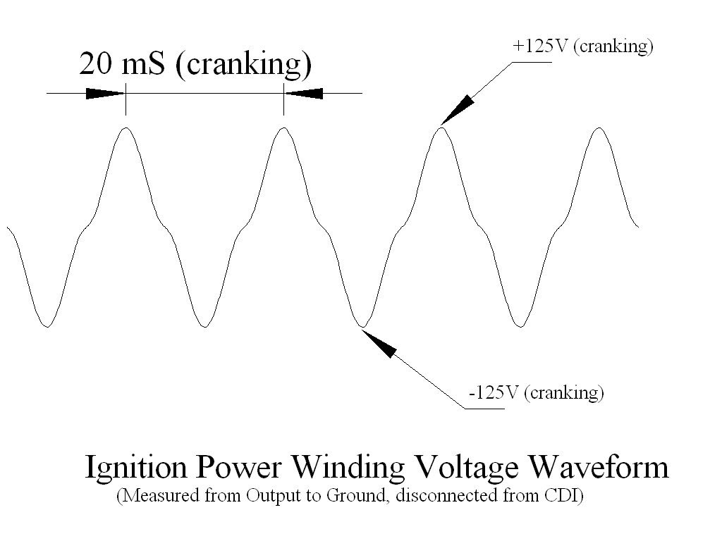
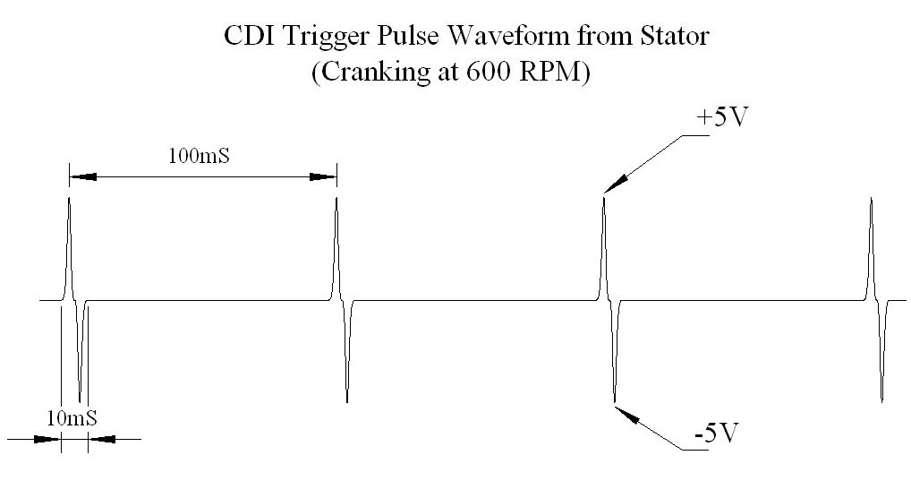
The stator, on the other hand is completely testable on the quad. They're a little more expensive, and harder to change. Thus I would measure the stator AC power output while cranking the engine. Ditto for the CDI trigger signal. Do you have an oscilloscope? Even a meter will work, but be sure to measure the stator outputs with the CDI unplugged. The reason for that is that the stator power winding output is yanked around a lot by the CDI making it very hard to determine if the CDI is bad, or the stator is bad. Note that D2 and D4 in your schematic short the stator output to ground when swinging negative, and D1 / C1 yank down on the stator output when swinging positive - at least until C1 charges up through the ignition coil primary.
If you have an oscilloscope here are some waveforms:
Jun 22, 2011 | 04:10 PM
#12

Thread Starter
|
Weekend Warrior
Joined: Jun 2011
Posts: 8
Likes: 0
Put in new bt151 transistor/cdi and then changed sparkplug and it fired up. i suspect it was more to do with spark plug it run for while then it wouldn't start for 20 to 30 mins then changed spark plug she runs good.
Jun 26, 2011 | 08:13 PM
#13
Thread Starter
|
Weekend Warrior
Joined: Jun 2011
Posts: 8
Likes: 0
Below is a revised circuit diagram of dt 125 for quadzilla cdi instructions and the other circuit is just a quick setup without pcb if you were to wire it bug style.
http://imageshack.us/f/52/sam4686.jpg/
http://imageshack.us/f/194/yamahadt125part2.png/


http://imageshack.us/f/52/sam4686.jpg/
http://imageshack.us/f/194/yamahadt125part2.png/

Thread
Thread Starter
Forum
Replies
Last Post
Currently Active Users Viewing This Thread: 1 (0 members and 1 guests)