
HOW TO: automatic reverse limiter removal and reverse lights
 Jan 30, 2011 | 10:50 AM
#1

Thread Starter
|
Weekend Warrior
Joined: Dec 2010
Posts: 12
Likes: 0
ok, so here is what you need to do the reverse override/ auto reverse light mod
two 4 pin relays (5 pin will work also, you wont use the center pin)
8 push on spade connectors (waterproof is preferred)
assorted wires (roughly 10 ft in different colors)
wire taps (10 pack will do)
SMALL 2 prong switch to use in diagnostic mode
BEFORE YOU WORK ON YOUR MACHINE BE SURE TO DISCONNECT THE BATTERY CABLES TO PREVENT ANY RISK OF SHORTING SOMETHING OUT!!!
start off in your shop or home with your relays and various wires and connectors in front of you
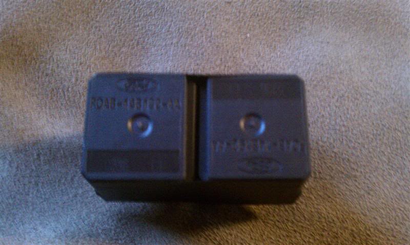
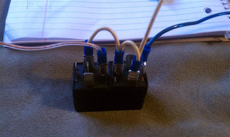
i stole mine from a parts truck i had out back. these are 5 pin relays. you only need 4 pin but the 5 pin works the same, you just dont use the center pin.
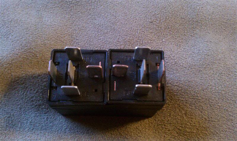
i used electrical tape to hold them together as shown. MAKE SURE YOU HAVE THE RELAYS IN THE SAME POSITION AS PICTURED WHEN YOU TAPE THEM TOGETHER
next you run a yellow wire as shown in the pictures. just twist the wires together and put them in the connectors. the wire coming off the relay is only about 12" long. this is going to be your power wire
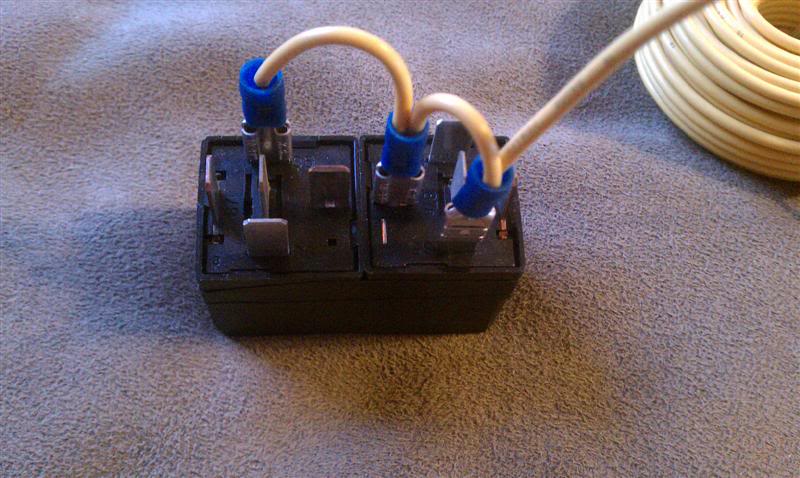
next connect a blue wire that is about 12" long as shown in this pic
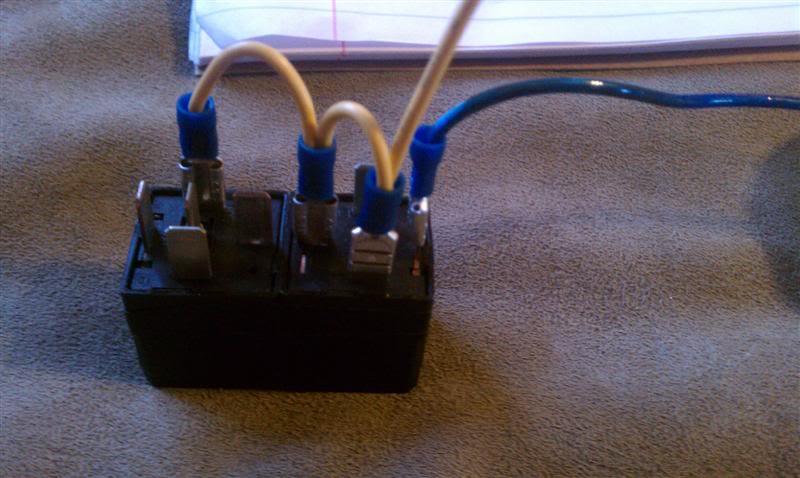
next step is your ground wire. i used a clear wire or you can use a brown wire if you want to make it easier to remember where it will be connected. this wire should be 12" long as well
next connect a wire as shown in the pic below. the wire that is loose on the relay with the blue wire needs to be about 4 feet long. (i only had a few wire colors so i used black tape to make some stripes on the long white wire to identify it from the other white wire) the loose wire on the relay with the brown ground wire only needs to be about 12" long
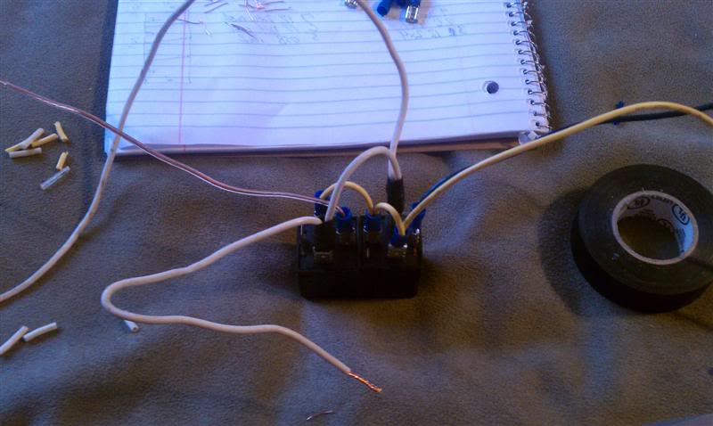
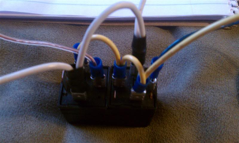
only one more wire to run on the relay pack! this wire needs to be about 4 feet long. (again due to limited wire colors i had i used a yellow wire and added tape to make striped to identify it.
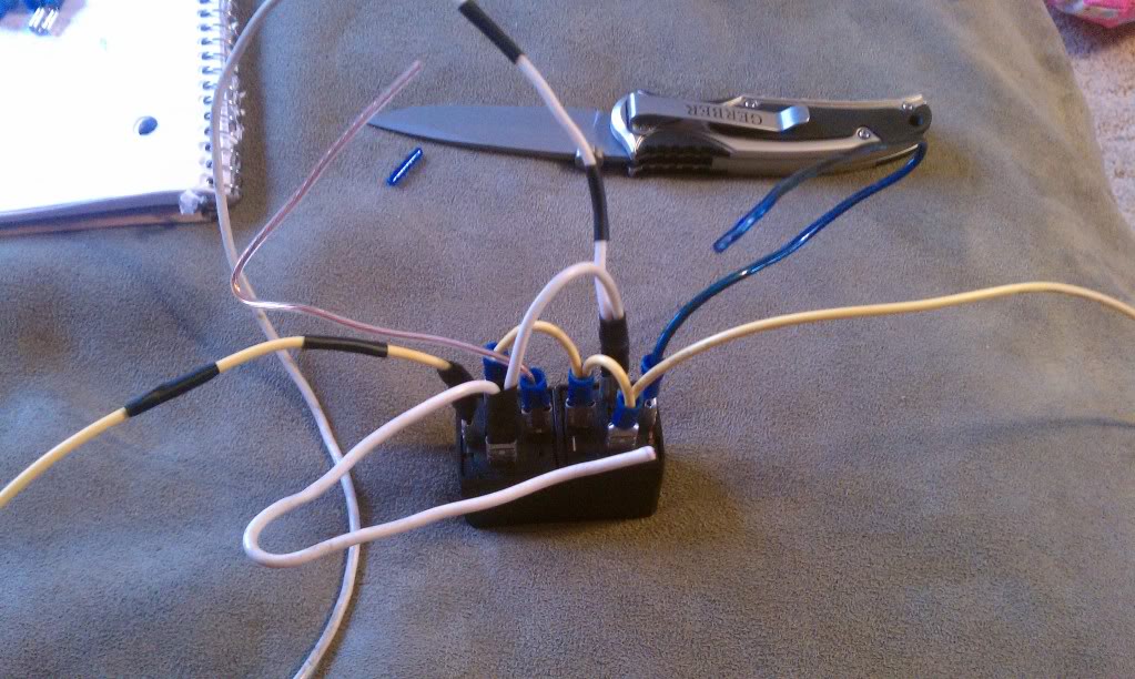
CONGRATS, THE HARD PART IS OVER AND YOU ARE READY FOR THE INSTALL!
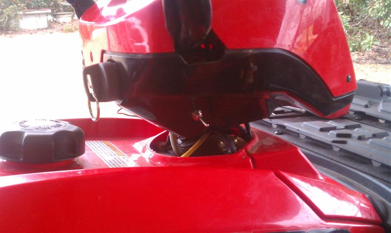
next pull the cover from your headlight pod and disconnect the speedometer and set it to the side.
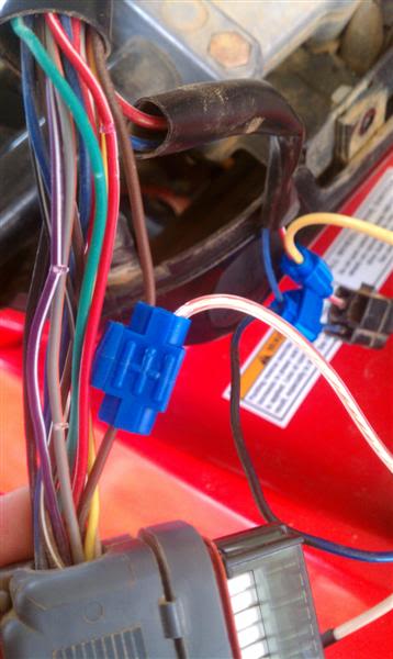
find the 2 wire harness that controls the work lights. it is a blue and red wire on my 2007 sportsman 800.
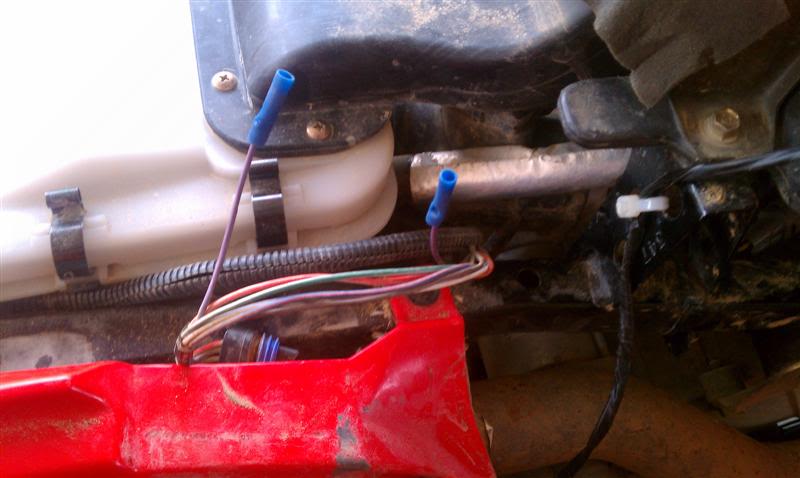
here are the 2 harnesses you need to access in the pod. the larger is the speedometer harness and the smaller is the work light harness.
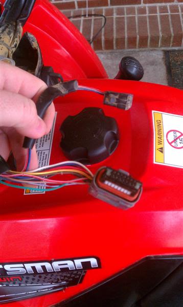
now connect the blue wire from your relay pack to the blue wire on the work light harness with a wire tap
next you will connect the power wire from your relay pack. THIS IS THE 12" YELLOW WIRE. NOT THE 4 FOOT WIRE WE PUT THE TAPE STRIPES ON!! this wire will connect to the RED wire in your work light harness
THIS IS WHERE YOUR SWITCH WILL COME INTO PLAY IF YOU DONT CARE ABOUT BEING ABLE TO USE DIAGNOSTIC MODE YOU CAN SKIP THIS STEP.
on the yellow power wire you just connected to the red wire in the work light harness go about 3 inches from the red wire connection and cut the yellow wire in half. you will now wire in your 2 prong switch to either side of the cut yellow wire.
THE ONLY REASON FOR THIS SWITCH IS TO ALLOW YOU TO ACCESS DIAGNOSTIC MODE. ALL LIMITERS ARE BYPASSED AUTOMATICALLY!!!
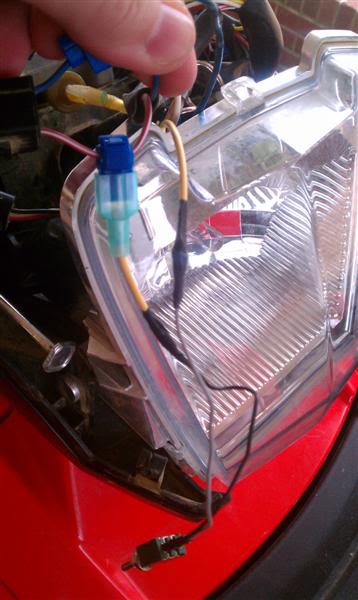
i mounted my switch out of the way since i will very rarely use it
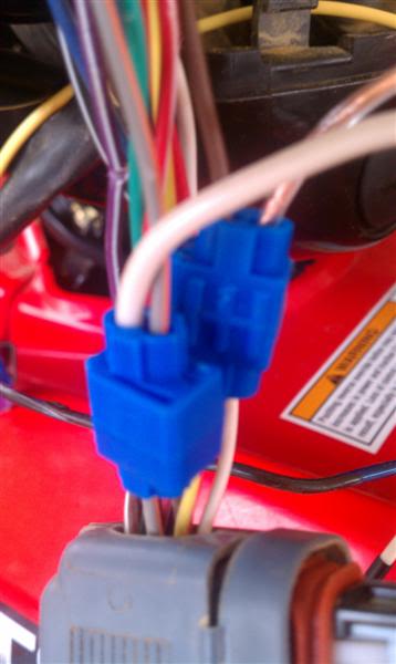
next you will connect the ground wire from your relay pack. this wire was the clear wire shown in the pics. you will use a wire tap to connect this wire to the BROWN wire in your SPEEDOMETER wiring harness
the last connection you will make in the pod is the SHORT WHITE WIRE. this is the 12" wire from your relay pack. it will be connected with a wire tap to the GRAY/orange stripe wire in your speedometer harness
YOU ARE NOW FINISHED
i used electrical tape to keep any connections in my relay pack from shorting out. make sure it is wrapped up good so water cant get in.
THE ONLY WIRES YOU HAVE LEFT ARE THE TWO LONG 4 FOOT WIRES FROM YOUR RELAY PACK. i taped these wires together with electrical tape to keep them held tightly together and make it look cleaner. only tape about 2 feet to leave yourself room to work with.
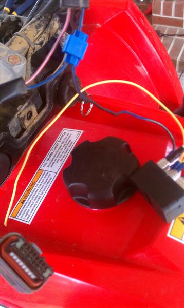
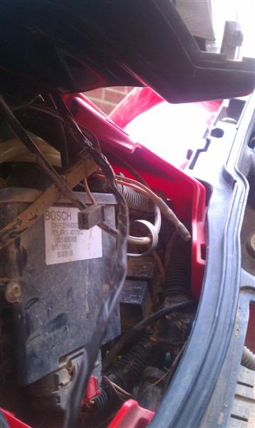
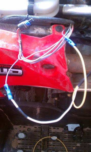
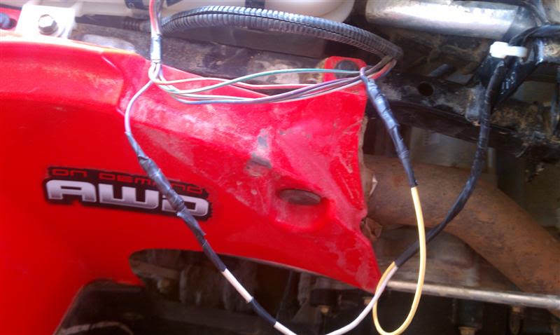
i ran these two wires down from the headlight pod down into the frame as shown.
next remove your seat and the black plastic that is on the side of your machine just under the gas tank.
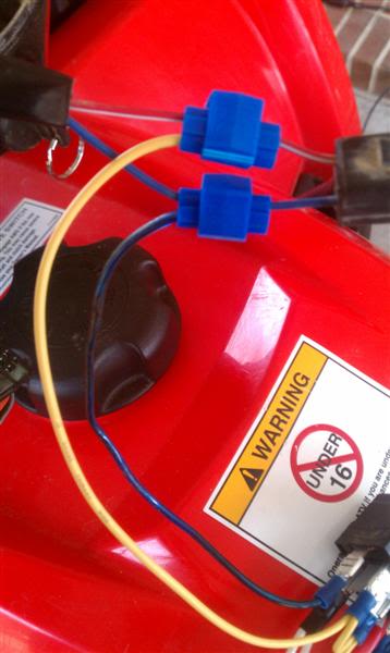
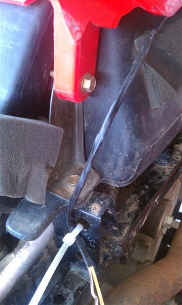
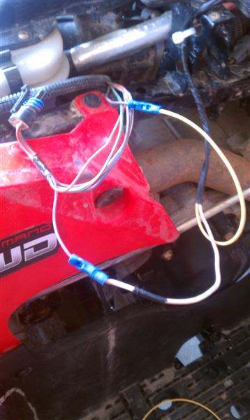
i ran the wires along the side of the frame by the gas tank as shown in the picture
a zip tie was used to hold them in place at the front of where the seat slides into place.
be sure to leave enough slack in the wires for full movement of the handle bars!!!!!!!!
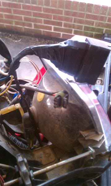
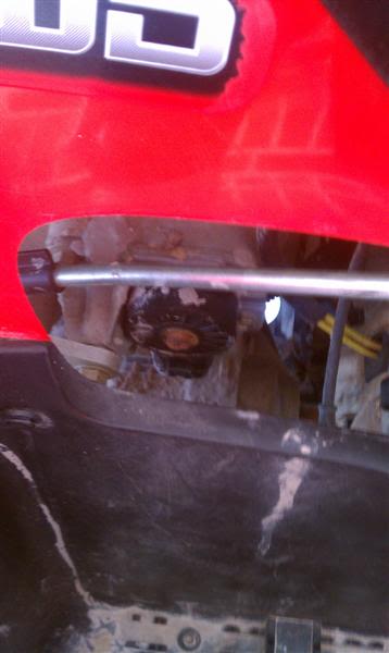
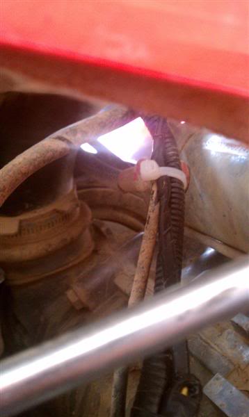
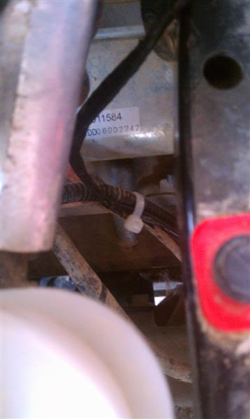
next find the transmission position sensor on the right side of your machine just under the shift linkage.
it is the black sensor shown in the pic
disconnect the harness and pull it up through the frame where the seat should be. you will have to remove the wire loom while you work on these wires. you may have to cut a zip tie from the harness to get enough room to work on everything
find the PURPLE WIRE in the transmission position sensor wire and cut it in half (MAKE SURE TO LEAVE ENOUGH ROOM TO WORK WITH ON BOTH ENDS!!!!!)
i used crimp on connectors on these wires.
THIS NEXT STEP IS VERY IMPORTANT. MAKE SURE THE WIRES ARE CONNECTED AS SHOWN. THIS MOD WILL NOT WORK IF THE WIRES ARE REVERSED!!!!!!!!
your yellow wire that we put the black stripes on will connect to the side of the purple wire that continues back into the wire loom towards the left side of your machine.
the white wire that we put the black stripes on will connect to the side of the purple wire that leads back to the harness end that you just unplugged.
next just tape up the crimp on connectors so water cant get in and corrode things.
next tuck all the wires back into the wire loom and finish taping up everything so all wires are protected
plug the transmission position harness back into the sensor making sure the wires are routed the same way they came out.
use zip ties to make sure none of the wires are going to touch the exhaust or rub the frame while you are riding.
looking down from the top
all that is left is to test everything out. connect your battery as normal, turn your key to the on position and shift the gear selector to reverse. the display should show "SLOW" and the work lights should come on automatically. if both of these dont happen check that your switch is in the ON position.
enjoy your new automatic bypass and the added functionality of your reverse lights.
my 800 was not equipped with the work light switch from the factory. this mod should work the same on one that has the work light switch.
while you are in any gear other than reverse you can make the reverse lights come on by holding that old annoying yellow button. the dash will show that the machine is in reverse but it will not affect anything. i have been riding 40 MPH and hit the yellow button and the display is just tricked into showing the "R" it will not throw the trans in reverse!
i tested this mod this past week and have not had any side affects from it.
if you need to use diagnostic mode simply turn your switch to the off position and everything will revert to they way it was from the factory.
when you want the reverse lights and limiters bypassed again simply turn the switch back on again
two 4 pin relays (5 pin will work also, you wont use the center pin)
8 push on spade connectors (waterproof is preferred)
assorted wires (roughly 10 ft in different colors)
wire taps (10 pack will do)
SMALL 2 prong switch to use in diagnostic mode
BEFORE YOU WORK ON YOUR MACHINE BE SURE TO DISCONNECT THE BATTERY CABLES TO PREVENT ANY RISK OF SHORTING SOMETHING OUT!!!
start off in your shop or home with your relays and various wires and connectors in front of you
i stole mine from a parts truck i had out back. these are 5 pin relays. you only need 4 pin but the 5 pin works the same, you just dont use the center pin.
i used electrical tape to hold them together as shown. MAKE SURE YOU HAVE THE RELAYS IN THE SAME POSITION AS PICTURED WHEN YOU TAPE THEM TOGETHER
next you run a yellow wire as shown in the pictures. just twist the wires together and put them in the connectors. the wire coming off the relay is only about 12" long. this is going to be your power wire
next connect a blue wire that is about 12" long as shown in this pic
next step is your ground wire. i used a clear wire or you can use a brown wire if you want to make it easier to remember where it will be connected. this wire should be 12" long as well
next connect a wire as shown in the pic below. the wire that is loose on the relay with the blue wire needs to be about 4 feet long. (i only had a few wire colors so i used black tape to make some stripes on the long white wire to identify it from the other white wire) the loose wire on the relay with the brown ground wire only needs to be about 12" long
only one more wire to run on the relay pack! this wire needs to be about 4 feet long. (again due to limited wire colors i had i used a yellow wire and added tape to make striped to identify it.
CONGRATS, THE HARD PART IS OVER AND YOU ARE READY FOR THE INSTALL!
next pull the cover from your headlight pod and disconnect the speedometer and set it to the side.
find the 2 wire harness that controls the work lights. it is a blue and red wire on my 2007 sportsman 800.
here are the 2 harnesses you need to access in the pod. the larger is the speedometer harness and the smaller is the work light harness.
now connect the blue wire from your relay pack to the blue wire on the work light harness with a wire tap
next you will connect the power wire from your relay pack. THIS IS THE 12" YELLOW WIRE. NOT THE 4 FOOT WIRE WE PUT THE TAPE STRIPES ON!! this wire will connect to the RED wire in your work light harness
THIS IS WHERE YOUR SWITCH WILL COME INTO PLAY IF YOU DONT CARE ABOUT BEING ABLE TO USE DIAGNOSTIC MODE YOU CAN SKIP THIS STEP.
on the yellow power wire you just connected to the red wire in the work light harness go about 3 inches from the red wire connection and cut the yellow wire in half. you will now wire in your 2 prong switch to either side of the cut yellow wire.
THE ONLY REASON FOR THIS SWITCH IS TO ALLOW YOU TO ACCESS DIAGNOSTIC MODE. ALL LIMITERS ARE BYPASSED AUTOMATICALLY!!!
i mounted my switch out of the way since i will very rarely use it
next you will connect the ground wire from your relay pack. this wire was the clear wire shown in the pics. you will use a wire tap to connect this wire to the BROWN wire in your SPEEDOMETER wiring harness
the last connection you will make in the pod is the SHORT WHITE WIRE. this is the 12" wire from your relay pack. it will be connected with a wire tap to the GRAY/orange stripe wire in your speedometer harness
YOU ARE NOW FINISHED
i used electrical tape to keep any connections in my relay pack from shorting out. make sure it is wrapped up good so water cant get in.
THE ONLY WIRES YOU HAVE LEFT ARE THE TWO LONG 4 FOOT WIRES FROM YOUR RELAY PACK. i taped these wires together with electrical tape to keep them held tightly together and make it look cleaner. only tape about 2 feet to leave yourself room to work with.
i ran these two wires down from the headlight pod down into the frame as shown.
next remove your seat and the black plastic that is on the side of your machine just under the gas tank.
i ran the wires along the side of the frame by the gas tank as shown in the picture
a zip tie was used to hold them in place at the front of where the seat slides into place.
be sure to leave enough slack in the wires for full movement of the handle bars!!!!!!!!
next find the transmission position sensor on the right side of your machine just under the shift linkage.
it is the black sensor shown in the pic
disconnect the harness and pull it up through the frame where the seat should be. you will have to remove the wire loom while you work on these wires. you may have to cut a zip tie from the harness to get enough room to work on everything
find the PURPLE WIRE in the transmission position sensor wire and cut it in half (MAKE SURE TO LEAVE ENOUGH ROOM TO WORK WITH ON BOTH ENDS!!!!!)
i used crimp on connectors on these wires.
THIS NEXT STEP IS VERY IMPORTANT. MAKE SURE THE WIRES ARE CONNECTED AS SHOWN. THIS MOD WILL NOT WORK IF THE WIRES ARE REVERSED!!!!!!!!
your yellow wire that we put the black stripes on will connect to the side of the purple wire that continues back into the wire loom towards the left side of your machine.
the white wire that we put the black stripes on will connect to the side of the purple wire that leads back to the harness end that you just unplugged.
next just tape up the crimp on connectors so water cant get in and corrode things.
next tuck all the wires back into the wire loom and finish taping up everything so all wires are protected
plug the transmission position harness back into the sensor making sure the wires are routed the same way they came out.
use zip ties to make sure none of the wires are going to touch the exhaust or rub the frame while you are riding.
looking down from the top
all that is left is to test everything out. connect your battery as normal, turn your key to the on position and shift the gear selector to reverse. the display should show "SLOW" and the work lights should come on automatically. if both of these dont happen check that your switch is in the ON position.
enjoy your new automatic bypass and the added functionality of your reverse lights.
my 800 was not equipped with the work light switch from the factory. this mod should work the same on one that has the work light switch.
while you are in any gear other than reverse you can make the reverse lights come on by holding that old annoying yellow button. the dash will show that the machine is in reverse but it will not affect anything. i have been riding 40 MPH and hit the yellow button and the display is just tricked into showing the "R" it will not throw the trans in reverse!
i tested this mod this past week and have not had any side affects from it.
if you need to use diagnostic mode simply turn your switch to the off position and everything will revert to they way it was from the factory.
when you want the reverse lights and limiters bypassed again simply turn the switch back on again

Thread
Thread Starter
Forum
Replies
Last Post
Currently Active Users Viewing This Thread: 1 (0 members and 1 guests)