Eton Viper 40E PLEASE HELP...ELECTRICAL ISSUES
#1
 08-29-2012, 01:14 PM


Join Date: Aug 2012
Posts: 5
Likes: 0
Received 0 Likes
on
0 Posts
 Ok so i'm stuck after reading a few posts. Its 2005 Viper RXL-40E (electric start). I got this off my brother in-law and it won't start. New parts i put on already are as follows: battery, spark plug, ignition coil, fuel filter, cleaned out carb completely, new Key and key switch since he didn't know where the keys were (but no remote for the remote shut down module which it has).
 Ok now the issue, i can't get it to start up. The electric starter works and turns the engine fine, the fuel is definitely getting to the cylinder because with the air filer assembly off i can see the fuel gather in the carb. My thoughts are that it has no spark. I bypassed the lanyard switch by just jumping the wires as i saw in a post and it cranks fine so that obviously worked..
I unplugged Remote Receiver Module and jumped the Blue/Yellow wire to the White/Black wire to eliminate that also and am getting voltage at the CDI while cranking so i assume that worked out fine also.
If i eletric start it, with the plug OUT against the block still connected to the coil wire, i get no arcing at all. i have .30-.40 volts on the white/black wire at the CDI and the same voltage at the White/Blue wire at the coil DURING cranking and 0 at no cranking.
i have even tried spraying ether as i crank it and i get nothing. I have tried to read these forums FIRST before bothering any of you but have failed to get it started again. We're leaving for mountains saturday so i wanted to get it started before then hopefully you guys can help. Any ideas are welcome
#2
08-29-2012, 10:24 PM
Join Date: Aug 2012
Posts: 5
Likes: 0
Received 0 Likes
on
0 Posts
#3
08-30-2012, 12:24 AM

Electrical Expert
Likes High Voltage In The Tub!
Likes High Voltage In The Tub!
Join Date: Dec 2008
Location: Tracy, California, USA
Posts: 3,260
Likes: 0
Received 12 Likes
on
12 Posts
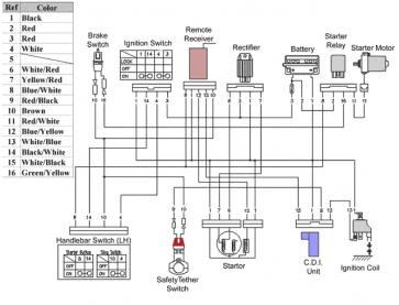
See if you can see if this matches your quad. At least the wire colors you jumped across match the wiring diagram I just posted.
...If i eletric start it, with the plug OUT against the block still connected to the coil wire, i get no arcing at all. i have .30-.40 volts on the white/black wire at the CDI and the same voltage at the White/Blue wire at the coil DURING cranking and 0 at no cranking.....
So how many pins on your CDI? Four? Are the colors Wht/Blk, Blk, Red/Blk, and Wht/Blu? If so you quad matches my diagram.
More tests (assuming the 4 pin CDI colors match up):
1) Unplug the CDI and make sure that the Tether switch plug is installed (or bypassed), the handlebar kill switch is in the "run" position, the ignition switch is "on", and the fuse is not blown. Then measure the DC voltage at the Red/Blk wire to the Blk wire at the CDI connector. Use the 20 volt scale. What do you measure?
2) Leave the CDI unplugged. Set your meter to measure resistance on the 2 or 20 ohm scale (not K ohms or M ohms). Measure the resistance of the Wht/Blu wire to the Blk wire. What do you measure?
#4
08-30-2012, 09:27 AM
Join Date: Aug 2012
Posts: 5
Likes: 0
Received 0 Likes
on
0 Posts
1) Unplug the CDI and make sure that the Tether switch plug is installed (or bypassed), the handlebar kill switch is in the "run" position, the ignition switch is "on", and the fuse is not blown. Then measure the DC voltage at the Red/Blk wire to the Blk wire at the CDI connector. Use the 20 volt scale. What do you measure?
As for this test, it was 12.26 volt reading
2) Leave the CDI unplugged. Set your meter to measure resistance on the 2 or 20 ohm scale (not K ohms or M ohms). Measure the resistance of the Wht/Blu wire to the Blk wire. What do you measure?
As for this test, i don't have 2 or 20 ohm scale on this crapppy meter i have, only 200 so i used that and got a reading of 0.5.
I was wonder, can the wires that go onto the coil (black and white/blue) be backwards? the coil was messed with by my brother in-law and i put the new coil in i just went off of how it was when i got it. if your standing at the back of the quad, the coil is on the right side and i noticed that coil has a black tab and green tab so i clearly put the black wire on the black tab.............
As for the wire diagram, yes that is exactly as my quad is set up.
#5
08-30-2012, 07:32 PM
Join Date: Aug 2012
Posts: 5
Likes: 0
Received 0 Likes
on
0 Posts
#6
08-30-2012, 11:32 PM
Electrical Expert
Likes High Voltage In The Tub!
Likes High Voltage In The Tub!
Join Date: Dec 2008
Location: Tracy, California, USA
Posts: 3,260
Likes: 0
Received 12 Likes
on
12 Posts
Answers embedded in blue:
As for this test, it was 12.26 volt reading [Good, you've got CDI power which is coming through the fuse, ignition switch, handlebar stop switch, and safety tether switch. That eliminates a lot of stuff.]
As for this test, i don't have 2 or 20 ohm scale on this crapppy meter i have, only 200 so i used that and got a reading of 0.5. [0.5 is OK - but does your meter on the same ohms setting and scale read 0.0 when you short the two leads together? If so, then good. But if it reads 0.5 with the leads shorted together that is another story... ]
]
I was wonder, can the wires that go onto the coil (black and white/blue) be backwards? the coil was messed with by my brother in-law and i put the new coil in i just went off of how it was when i got it. if your standing at the back of the quad, the coil is on the right side and i noticed that coil has a black tab and green tab so i clearly put the black wire on the black tab............. [I doubt it, but it wouldn't hurt to try... The reason I doubt it is that if your coil wiring was backwards your coil primary resistance would read 0.0 ohms, not 0.5. But see my comments above...") ]
]
As for the wire diagram, yes that is exactly as my quad is set up.
As for this test, it was 12.26 volt reading [Good, you've got CDI power which is coming through the fuse, ignition switch, handlebar stop switch, and safety tether switch. That eliminates a lot of stuff.]
As for this test, i don't have 2 or 20 ohm scale on this crapppy meter i have, only 200 so i used that and got a reading of 0.5. [0.5 is OK - but does your meter on the same ohms setting and scale read 0.0 when you short the two leads together? If so, then good. But if it reads 0.5 with the leads shorted together that is another story...
]I was wonder, can the wires that go onto the coil (black and white/blue) be backwards? the coil was messed with by my brother in-law and i put the new coil in i just went off of how it was when i got it. if your standing at the back of the quad, the coil is on the right side and i noticed that coil has a black tab and green tab so i clearly put the black wire on the black tab............. [I doubt it, but it wouldn't hurt to try... The reason I doubt it is that if your coil wiring was backwards your coil primary resistance would read 0.0 ohms, not 0.5. But see my comments above...
]As for the wire diagram, yes that is exactly as my quad is set up.
#7
08-30-2012, 11:34 PM
Electrical Expert
Likes High Voltage In The Tub!
Likes High Voltage In The Tub!
Join Date: Dec 2008
Location: Tracy, California, USA
Posts: 3,260
Likes: 0
Received 12 Likes
on
12 Posts
Trending Topics
#8
08-30-2012, 11:51 PM
Electrical Expert
Likes High Voltage In The Tub!
Likes High Voltage In The Tub!
Join Date: Dec 2008
Location: Tracy, California, USA
Posts: 3,260
Likes: 0
Received 12 Likes
on
12 Posts
Whenever troubleshooting difficult problems I find that constantly revisiting old test results and verifying them again is very helpful in the long run. Three steps forward, and two back, works the best for me. It is so easy to make a simple mistake, not notice it, and then based on faulty data go off on a wild goose chase - which ends in total frustration. I'm convinced that the reason people fail to fix electrical problems is that they don't do the "go back and verify that" approach and get on the wrong path with no way to back to the right path.
Or, a measurement error causes one to fixate on it being an electrical problem when in fact it isn't. Perhaps the "spark test" was done with the kill switch on - even though you could swear on a bible that that cannot have happened. I've done that.
This is a testing philosophy post - and not specific to your problem. But I notice you've done a lot of things while troubleshooting your quad that could also be a problem too.
So have you verified recently that you really do (still) have a no spark problem? I'm just making sure...
#9
08-31-2012, 12:05 AM
Electrical Expert
Likes High Voltage In The Tub!
Likes High Voltage In The Tub!
Join Date: Dec 2008
Location: Tracy, California, USA
Posts: 3,260
Likes: 0
Received 12 Likes
on
12 Posts
Another test:
Hook the CDI up, turn on the ignition, set all kill switches to the run position. Set your meter to measure AC volts on the 20 volt scale (or probably 200 volt scale in your case). Measure the AC voltage from the White/Blue wire to engine ground while cranking the starter motor. You can measure this at the ignition coil or the CDI (same wire). If necessary use a sewing pin to probe into the connector (or wire) - just keep your fingers out of the circuit while doing any measurements.
What do you measure? Steady voltage? Zero Volts? Bouncing around voltage? Describe in detail what you see...


Thread
Thread Starter
Forum
Replies
Last Post
Currently Active Users Viewing This Thread: 1 (0 members and 1 guests)