
kazuma 90 panda i think help everything wrong
 Jul 14, 2010 | 12:24 AM
#11

Electrical Expert
Likes High Voltage In The Tub!
Likes High Voltage In The Tub!
Joined: Dec 2008
Posts: 3,260
Likes: 14
From: Tracy, California, USA
This has been really puzzling, but maybe it isn't so puzzling anymore. Check this link to a panda 90cc "coil":
Ignition Coil Kazuma Panda 90cc - Panda 90cc (2-stroke) Parts - Kazuma Quad Bike Parts - Spare Parts ? PetrolScooter UK
Notice how this "coil" matches your coil pic's, and it has too many wires also - same as you reported on yours. This isn't a coil. It is a coil/CDI *combination*. The CDI is built into this device.
Forget the other links. Nothing from them matches your quad. Let's start fresh.
A CDI absoutely needs 4 wires to work:
1) Power (AC or DC)
2) Ground
3) Timing Trigger
4) Output pulse to coil
In addition many CDI's have a kill input that kills the spark to shut down the quad. Some short this pin to ground to kill the spark, others require a ground to enable spark. We'll come back to this...
The output pulse to your coil is made inside the combination device on your quad. It does not need to come outside. So that leaves maybe three wires (plus a kill switch makes 4).
The power pin (1) comes from the stator if it is AC powered. Blk/red is the common color for this. You have a blk/red coming from your stator and a blk/red wire on your coil/cdi combo.
The timing/trigger wire (3) comes from the stator. You have a red/wht wire on the coil/cdi, and a wht/red on the stator. Of course that is the stator pigtails. What is more important is the wire harness colors. Does the wht/red stator wire connect to a Red/wht wire in the harness? I'm thinking this is the timing trigger connection. Use a meter to see if these wires are tied together.
There is a black wire on the coil/cdi (2) , and a black wire on the stator. I'm thinking this is ground. Use a meter to check for continuity to ground and each other.
Finally the kill switch. Blk/wht is the standard color. You show this wire going to the handlebar (I think that's what "h/b" means). But I don't yet know whether you kill switch need to be shorted to ground to get spark, or open to get spark. But this is just one piece of the puzzle. We also need to see if your CDI is getting power from the stator, and getting trigger signal from the stator.
Use a meter to measure the Wht/red wire resistance to ground. What do you measure? 150 ohms would be what I would expect - but I don't know for sure since this is completely unknown territory. More info translates into better ideas I hope...
Measure the resistance of the Blk/red wire to ground. What do you see? 450 ohms is the answer for generic chinese quads, but once again this is just gathering more info...
Measure the resistance of the black/white wire at the coil/cdi to ground. Do this for both all switches in the "run" position (plus ignition "on"), and also with all kill switches off (and ignition off). What do you measure for both conditions?
So what about the dangling wires? I don't know yet, but maybe they were part of a remote control module that was disconnected. Tape those wire up for now, and we'll come back to them.
Lets test/verify the above, then the next step will be to measure the power to the CDI, and trigger voltages. Also based on your kill switch measurent results we may to look there too.
Dec 12, 2011 | 11:17 PM
#13
Electrical Expert
Likes High Voltage In The Tub!
Likes High Voltage In The Tub!
Joined: Dec 2008
Posts: 3,260
Likes: 14
From: Tracy, California, USA
You really can't do anything but simple testing on a coil, such as measuring the primary and secondary winding resistances. This will reveal only catastrophic failures such as open windings, or dead shorted windings.
You can't measure things such as shorted turns in the windings, or high voltage breakdown without special equipment. Thus the general rule is you check for resistances, then replace the coil.
But why are you looking at just the ignition coil? The ignition system consists of many things such as the stator, CDI, and kill switch wiring - a lot of which can be measured with a meter. Have you done any of this yet?
What chinese quad? 4 stroke or 2 stroke? Engine size? How many pins on the CDI?
Dec 13, 2011 | 11:22 PM
#16
Electrical Expert
Likes High Voltage In The Tub!
Likes High Voltage In The Tub!
Joined: Dec 2008
Posts: 3,260
Likes: 14
From: Tracy, California, USA
 .
.You'll need a meter to go from here. Following is the generic procedure for testing the 5 pin CDI ignition system. Obviously you can skip the "disconnecting the kill switch" section because you've already done that.
When testing the stator it is really important to do both the resistance and voltage checks (for both AC ignition power and timing trigger signal). Neither one by itself is conclusive in many cases, I need both voltage and resistances...
Is this a picture of your CDI?
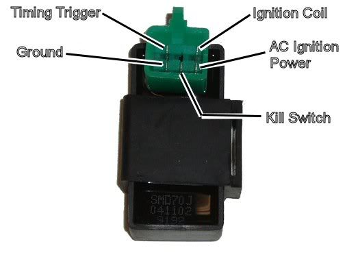
Assuming the answer is yes, the first thing to do is eliminate all kill switches and kill switch wiring:
Method 1) Unplug the CDI and remove the kill switch pin in the CDI connector on the wiring harness. The pin is held in with a spring tab on the pin itself. You'll have to probe into the connector and push this tab in order to extract the pin. Plug the CDI back in (kill switch wire dangling) and see if you have spark.
Method 2) Unplug the CDI. Turn on the ignition switch and set all kill switches to the run position. Use a meter to measure resistance in of the kill switch pin in the wiring harness connector to engine/frame ground. If the reistance is infinite on the 100K ohm scale then your kill switches/kill switch wiring are OK. If you measure zero ohms then you have a kill switch/wiring issue.
The other inputs your CDI needs to make spark are AC Ignition Power, and the Trigger signal. Do the following:
1) Unplug the CDI. In the wiring connector measure the resistance of the AC Ignition Power pin to the Ground pin. You should see 400 ohms or so. What do you measure?
2) Measure the resistance of the Timing/trigger pin to the ground pin. You should measure 150 ohms or so. What do you measure?
3) Leave the CDI unplugged. Set your meter to measure AC volts on the 100 volt scale. Measure the voltage on the AC Ignition Power pin to the ground pin while cranking the engine. You should see 40 to 80 volts AC while the engine is cranking. What do you measure?
4) Set your meter to measure AC volts on the lowest scale you have. Ideally this would be 2 volts but many meters don't go down this low. In that case use the lowest scale you have. Measure the voltage on the Timing Trigger pin to the Ground pin while cranking the engine. You should 0.2 t0 0.4 volts AC. What do you measure?
Now for measuring the output side of the CDI:
A) Leave the CDI unplugged. In the CDI wiring connector measure the resistance of the Ignition Coil pin to the ground pin. You should measure less than 1 ohm (but not zero ohms). What do you measure?
B) Plug the CDI back in. Set your meter to measure AC volts on the 20 volt scale. Set all kill switches to the run position. Crank the engine while measuring the voltage on the Igntition Coil pin to ground. Poke through the insulation of the wire if you can't probe the connector.
Caution: There should be moderately high voltage spikes on this wire. Make sure your fingers are not part of the circuitry. Don't touch the probe lead tips while doing this test.
What you should see is a lot of random numbers with lots of zero values as well. This is because the meter may catch all or part of the spark event voltage, with a lot of nothing in between. Describe what you see.
Note: Using a meter to measure this point produces highly variable results depending on the meter. What you really need is an oscilloscope, but most always a meter is all that is available. We have to do the best we can with what's available. Describe the meter results as accurately as you can - there is information there to analyze....
Dec 15, 2011 | 03:28 PM
#17

Weekend Warrior
Joined: Dec 2011
Posts: 6
Likes: 0
thanks so much for the info on testing the stator and cdi but i am having problems if i hook up the kill switch it wrecks the cdi lucky i bought tw0 .now i have the quad runing but i am nervis to hook up the kill switch because last time it blew the cdi do you have any ideas why the kill switch would blow the cdi thanks so much for yer help
Dec 15, 2011 | 10:54 PM
#18
Electrical Expert
Likes High Voltage In The Tub!
Likes High Voltage In The Tub!
Joined: Dec 2008
Posts: 3,260
Likes: 14
From: Tracy, California, USA
thanks so much for the info on testing the stator and cdi but i am having problems if i hook up the kill switch it wrecks the cdi lucky i bought tw0 .now i have the quad runing but i am nervis to hook up the kill switch because last time it blew the cdi do you have any ideas why the kill switch would blow the cdi thanks so much for yer help
So why do you think your CDI's are getting blown up?
We are jumping all over the map here. First it's your coil, then CDI and/or stator, and now you have blown up CDI's. And no tests have been done yet. Is your wiring intact (as in from the factory), or has there been some creative wiring done on this quad?
If you think your kill switches aren't wired right then measure them. When all kill switches are in the "run" position the kill switch wire should have no connection to ground (use a meter to measure the resistance). When *any* kill switch is set to the "kill" position the kill switch wire is shorted to ground. Again use a meter. Possible kill switches are:
1) left handerbar kill switch
2) ignition switch (on=run, off = kill)
3) tether cord pull kill switch
4) remote control module (unplug to guarantee "run" position)
Dec 16, 2011 | 07:29 AM
#19
Weekend Warrior
Joined: Dec 2011
Posts: 6
Likes: 0
i did all the tests that you had sent me with multi meter the tests indecated to me that the stator was working fine exept the triger wire was only135.5 ohms not 150 like you had said so i changed the cdi ran got spark right away whent for short ride shut it off and when i tried to restart no spark so i repeated all the tests that you had sent me and found that the cdi was not working again so i once again put on a new cdi and quad runs with good spark but i have left the kill switch unhooked because the last time it blew the cdi ...i am going to test the kill switch like you have discrebed and yes this quad has a home made wiring harness by me the only safty left is the kill and the pull off switch witch i have grounded one side and put the other to the kill pin on the cdi.
Thank you so much for the great feedback!!! your help is indespencible!!!
Thank you so much for the great feedback!!! your help is indespencible!!!
Dec 16, 2011 | 10:36 PM
#20
Electrical Expert
Likes High Voltage In The Tub!
Likes High Voltage In The Tub!
Joined: Dec 2008
Posts: 3,260
Likes: 14
From: Tracy, California, USA
I think the failure of your second CDI had nothing to with the kill switch input getting grounded. More likely you just bought a CDI that is defective. The problem is that CDI's are built in huge batches, so if all the CDI's in that batch have the same problem (fails after a couple minutes), don't buy another CDI from the same source. They could have thousands of bad ones just waiting to be off loaded... It's been reported before on this forum: Five bad CDIs in a row, then after buying a CDI from another source all problems solved.
Do check that your kill switch wiring only grounds the kill switch wire in the "kill" position, and is open (disconnected) in the "run" position. It should not be doing something like applying 12 volts to the kill switch pin in the "run" position...
I'm impressed that you were able to make your own wiring harness and get the quad running...
i did all the tests that you had sent me with multi meter the tests indecated to me that the stator was working fine exept the triger wire was only135.5 ohms not 150 like you had said so i changed the cdi ran got spark right away whent for short ride shut it off and when i tried to restart no spark so i repeated all the tests that you had sent me and found that the cdi was not working again so i once again put on a new cdi and quad runs with good spark but i have left the kill switch unhooked because the last time it blew the cdi ...i am going to test the kill switch like you have discrebed and yes this quad has a home made wiring harness by me the only safty left is the kill and the pull off switch witch i have grounded one side and put the other to the kill pin on the cdi.
Thank you so much for the great feedback!!! your help is indespencible!!!
Thank you so much for the great feedback!!! your help is indespencible!!!