
Marshin MHT-200 no spark???
 Sep 23, 2011 | 12:23 PM
#1

Thread Starter
|
Trailblazer
Joined: Oct 2007
Posts: 69
Likes: 0
Well, here's what I got....first off, the CDI is the one with 2 plugs, one 4 pin and one 2 pin. It only uses one wire on the 2 pin side tho. I was able to measure ~1 volt on the primary side of the coil and 1.5 ohms resistance. Was not able to check the kill switch, so I cut the wires (never use it and it's a pain anyway). Should the kill switch wires be Open or closed? I have a new coil coming next week and replaced the cdi with no results. I'm not much of a quad electrician, I'm a high tonnage injection molding maintenance tech. From the 10 or so generic chinese prints that are close, it appears that this is an ac cdi and the only components are the kill switch, key switch, cdi, and the coil. It does turn over, just no spark. Any help with this problem is GREATLY appreciated, and if we can get it running I bow to you!!!!!
Sep 24, 2011 | 12:37 AM
#2

Electrical Expert
Likes High Voltage In The Tub!
Likes High Voltage In The Tub!
Joined: Dec 2008
Posts: 3,260
Likes: 14
From: Tracy, California, USA
Most 6 pin CDIs that have only one wire on the 2 pin connector are DC powered - not AC powered. Probably the first step you want to do is use a meter to find out whcih CDI you have. Here is a procedure for doing that:
Some additonal comments:
Just exactly what wire(s) did you cut? Where, and what color(s) where they? If your CDI only has one wire on the 2 pin connector you cannot have the standard kill switch system since the one wire on that 2 pin connector *must* be the power wire (AC or DC still to be determined) since the quad cannot run without power. There are other ways to wire in a kill switch other than the standard connection to the CDI kill input (which, BTW, requires an open to run, and a short to ground to kill the spark). But these other ways can use a short or an open to kill spark depending on how it is wired.
Again, only one wire on the CDI 2 pin connector points toward a DC powered CDI. Use a meter and the procedure above to find out. That will narrow down the possibilites and point the way forward from here.
I would add to the components you listed:
1) Stator - incuding AC power if CDI is AC powered, but in any case the trigger signal also comes from the stator, and is very necessary)
2) All the wiring too and from these needed parts.
3) Spark Plug.
The 2 plug 6 wire CDIs come in two different designs. One is powered off 12 volts DC, and the other is powered off a moderately high voltage AC which comes from the stator. Unfortunately there is no reliable way to tell the difference between the two by just looking at them. To be sure you need to use a meter to find out which you have:
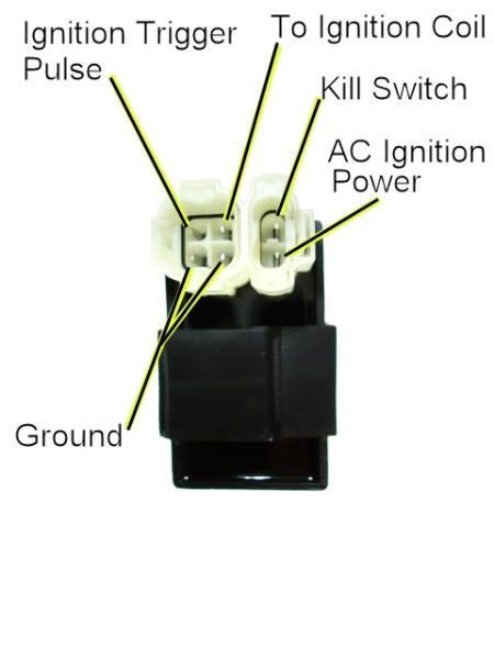
1) Unplug the CDI, and turn on the ignition. Do not crank the starter motor. Use a meter to measure the *DC* voltage on the pin labeled "AC ignition power" in the wiring harness to both ground pins in the 4 pin CDI connector. If you measure 12 volts DC then you have a DC powered CDI.
2) If you don't measure 12 volts DC on the ignition power pin, then switch the meter over to measure AC volts on the 200 volt scale. While cranking the starter motor, measure the AC voltage on the "AC Ignition Power" pin to the the Ground pin. You should see 40 to 80 volts AC. If you measure AC voltage when the starter is turning then you have an AC powered CDI.
Using a meter is the only 100% reliable way to figure out if your CDI is AC or DC powered. But there are some clues you can use that are usually (but not always) correct:
A) DC CDIs tend to be a little larger than their AC powered counterpart. This is because the DC powered CDI needs a bunch more circuitry to convert the 12 volts DC to the moderately high voltage supply that all CDIs must have.
B) Most (but not all) DC powered quad ignition systems do not use the kill switch input pin. The CDI connector pin usually has no wire tied to it. AC powered quad ignition systems usually do use the kill switch input pin.
I would add to the components you listed:
1) Stator - incuding AC power if CDI is AC powered, but in any case the trigger signal also comes from the stator, and is very necessary)
2) All the wiring too and from these needed parts.
3) Spark Plug.
Sep 26, 2011 | 05:28 PM
#3
Thread Starter
|
Trailblazer
Joined: Oct 2007
Posts: 69
Likes: 0
Thank you Lynn...I'll get the voltage checks done and more info on the kill switch circuit in a couple of days. Getting a bunch of OT right now and gotta make hay while the sun shines!
Denny
The kill switch wires that I cut were blue/white stripe and green. I cut them, right at the kill switch. The blue/white wire goes back to a relay in Batt box that controls the starter (not the starter solenoid). It is called a starter relay in the parts list, prolly wired thru the brake and neutral switches. The outs on it appear to go to the starter solenoid.
Sep 27, 2011 | 12:16 AM
#4
Electrical Expert
Likes High Voltage In The Tub!
Likes High Voltage In The Tub!
Joined: Dec 2008
Posts: 3,260
Likes: 14
From: Tracy, California, USA
Yes, do the voltage measurements. It will be enlightening... Your job comes first of course  .
.
Blue/white is a classic color for the timing trigger signal from the stator to the CDI. Green is a classic color for ground. Shorting the trigger signal (blue/white wire) to ground (green wire) is a perfectly legitimate way to kill the spark (though not the most common way). This part doesn't seem too far afield, and it could explain why you don't have the conventional kill switch input to the CDI. And it also gives more credence to a DC powered CDI scenario (but not 100%)...
But the rest of your post about relays controlling the starter (but not the starter solenoid) makes no sense at all to me. I think we have some further work to do on this part down the road . Get the measurements outlined previously first, then let's go from there...
.Blue/white is a classic color for the timing trigger signal from the stator to the CDI. Green is a classic color for ground. Shorting the trigger signal (blue/white wire) to ground (green wire) is a perfectly legitimate way to kill the spark (though not the most common way). This part doesn't seem too far afield, and it could explain why you don't have the conventional kill switch input to the CDI. And it also gives more credence to a DC powered CDI scenario (but not 100%)...
But the rest of your post about relays controlling the starter (but not the starter solenoid) makes no sense at all to me. I think we have some further work to do on this part down the road
. Get the measurements outlined previously first, then let's go from there...
Sep 29, 2011 | 05:08 PM
#5
Thread Starter
|
Trailblazer
Joined: Oct 2007
Posts: 69
Likes: 0
Major brain fart, Lynn...It has 3 "relays" and the starter solenoid. I don't have a print and can't find one. I have 3 that appear to be close. Made it out to the garage today. I don't know that those relays are SSR's, but they are sealed. I tried to jump the output on one out last week and it turned the starter over. The blue/white kill switch wire goes to this relay as well as a couple of other wires. I plan on trying some voltage checks at the CDI plug and coil tomorrow before work. What kind of voltage should I see at the primary wire on the coil? I am pretty sure the CDI is DC now as it's half again bigger than the replacement and only has the one battery lead. I'll post a copy of this in the original "Ask an Expert" thread so it doesn't get chopped up.
Thanks
Denny
Thanks
Denny
Sep 30, 2011 | 11:09 AM
#6
Thread Starter
|
Trailblazer
Joined: Oct 2007
Posts: 69
Likes: 0
Lynn...got out to do the checks this morning and here's what I found
1st...Both engine ground wires at the plug (unhooked)(green and green/white) were 5 ohms.
2nd...CDI power, solid black, was 12.5VDC (unhooked).
3rd...Black wire with white stripe goes to ignition pulse. I'll have to check my shop meter, as the home meter lowest scale was 20VAC (unhooked).
4th...Black wire with yellow stripe goes to coil primary. With kill switch wired closed, zero volts. With kill switch open showed varying voltages of ~4VDC to ~.5VDC with the CDI plugged in while cranking the engine. I am assuming that the varying voltages are the result of the CDI charging/discharging while cranking the engine.
The coil is defintely DC as it is one wire, internally grounded.
I have a spare coil now, one wire primary, that looks exactly like the one that's on it. Old coil primary windings showed 1 ohm to ground. New coil primary showed 1.2 ohms.
That's all I know for now. We'll figure out those batt box relays later if need be. I'll be carefull and write what I see, not what I thought I saw!
Much thanks again!
Denny
Oct 1, 2011 | 06:01 PM
#7
Electrical Expert
Likes High Voltage In The Tub!
Likes High Voltage In The Tub!
Joined: Dec 2008
Posts: 3,260
Likes: 14
From: Tracy, California, USA
My comments embedded in blue...
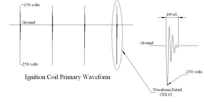
Here is a drawing showing what the ignition coil primary voltage looks for most CDI's I've seen. Time is on the X axis, the voltage on the Y axis. Note the very narrow bursts of high voltage AC, which gets stepped up to many thousands of volts in the coil secondary winding and fires the plug. There are other possible waveforms that can be used to fire the plug through the ignition coil, but this by far is the most common.
Lynn...got out to do the checks this morning and here's what I found
1st...Both engine ground wires at the plug (unhooked)(green and green/white) were 5 ohms. [This seems really high. It should be more like 0.1 ohms]
2nd...CDI power, solid black, was 12.5VDC (unhooked). [This proves that your CDI is DC powered]
3rd...Black wire with white stripe goes to ignition pulse. I'll have to check my shop meter, as the home meter lowest scale was 20VAC (unhooked). [Are you sure it is not blue/white? Black/white is usually a kill switch color. If it is black/white and does hook up to the trigger pin of the CDI then so be it. In any case be sure to measure the cranking AC voltage here as well as the resistance on this wire to ground (engine stopped). Both have read correct to rule out triggering problems]
4th...Black wire with yellow stripe goes to coil primary. With kill switch wired closed, zero volts. With kill switch open showed varying voltages of ~4VDC to ~.5VDC with the CDI plugged in while cranking the engine. I am assuming that the varying voltages are the result of the CDI charging/discharging while cranking the engine. [The voltages here are complicated because when the CDI is firing the voltages here vary tremendously and very quickly. Meters are designed to measure this kind of moving voltage, and so different meters behave differently. Most meters on AC volts will measure mostly zero volts with random numbers interspersed as the meter happens to capture all or part of the very narrow high voltage burst that comes out. ]
The coil is defintely DC as it is one wire, internally grounded. [Ignition coils are never DC. The ignition coil is a transformer - and transformers only will pass through changing voltages ]
I have a spare coil now, one wire primary, that looks exactly like the one that's on it. Old coil primary windings showed 1 ohm to ground. New coil primary showed 1.2 ohms. [That is probably OK]
That's all I know for now. We'll figure out those batt box relays later if need be. I'll be carefull and write what I see, not what I thought I saw!
Much thanks again!
Denny
Trending Topics
Oct 5, 2011 | 11:48 AM
#8
Thread Starter
|
Trailblazer
Joined: Oct 2007
Posts: 69
Likes: 0
Turns out that the coil secondary side was not passing spark. Picked up a cheapo analog meter and was able to pick up the voltages the digital missed. After changing the coil, it still wouldn't start. Did about an hours worth of wire and switch testing, then realized I hadn't connnected the primary coil wire. (Embarrased Emoticon!)(Really hate to admit that part, but it was significant!) After drying the gas soaked plug out, fired right up. Thank you Lynn for all your help, I really appreciate it!
Denny
Denny

Thread
Thread Starter
Forum
Replies
Last Post
fordfaithful21
Polaris Ask an Expert! In fond memory of Old Polaris Tech.
9
Dec 7, 2015 05:52 PM
Cdenton
Technical and How-To Articles
1
Sep 9, 2015 11:23 AM
Currently Active Users Viewing This Thread: 1 (0 members and 1 guests)