
Reverse switch
 Jan 13, 2012 | 12:09 AM
#1

Thread Starter
|
Weekend Warrior
Joined: Jan 2012
Posts: 5
Likes: 0
New member and new owner of a Baja WD250U that does not run. I have aquired a cd from Baja that has the service manual on it. I have not been thru all the components as of yet. I do have a couple of questions.
1. Where is the reverse switch located?
2. Where can you buy plastic parts for this unit?
3. I have checked lights, brake lights from both foot and handle, key switch, run switch, and unit will turn over with electric starter but no spark.
Previous owner said they went into some water and it stopped running sometime later.
What is the best way to attack this problem? I hate to junk this thing but it sounds like these are a lot of trouble......
Jan 13, 2012 | 11:14 PM
#2

Electrical Expert
Likes High Voltage In The Tub!
Likes High Voltage In The Tub!
Joined: Dec 2008
Posts: 3,260
Likes: 14
From: Tracy, California, USA
I'm not familiar with your quad specifically, but am wondering about the "reverse" switch... I've looked at one published baja250 wiring diagram and don't see anything like this. Are you sure you have a "reverse switch", and why are you interested in finding it?
I have no idea about plastic parts, other than contacting Baja Motorsports.
The starter motor turns, so the brake switch starter safety interlock is working (or it is bypassed). No spark is a completely different issue. Do you know if your CDI is AC powered or DC powered? The troubleshooting procedure is different depending on which you have. Here is the generic procedure for mesuring whether you have a DC or AC powered CDI:
The 2 plug 6 wire CDIs come in two different designs. One is powered off 12 volts DC, and the other is powered off a moderately high voltage AC which comes from the stator. Unfortunately there is no reliable way to tell the difference between the two by just looking at them. To be sure you need to use a meter to find out which you have:
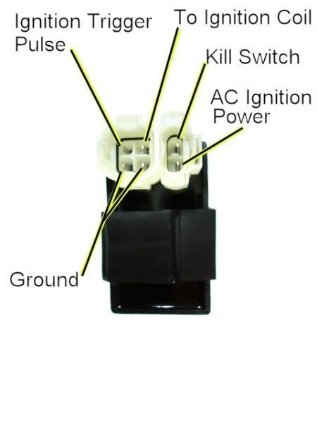
1) Unplug the CDI, and turn on the ignition. Do not crank the starter motor. Use a meter to measure the *DC* voltage on the pin labeled "AC ignition power" in the wiring harness to both ground pins in the 4 pin CDI connector. If you measure 12 volts DC then you have a DC powered CDI.
2) If you don't measure 12 volts DC on the ignition power pin, then switch the meter over to measure AC volts on the 200 volt scale. While cranking the starter motor, measure the AC voltage on the "AC Ignition Power" pin to the the Ground pin. You should see 40 to 80 volts AC. If you measure AC voltage when the starter is turning then you have an AC powered CDI.
Using a meter is the only 100% reliable way to figure out if your CDI is AC or DC powered. But there are some clues you can use that are usually (but not always) correct:
A) DC CDIs tend to be a little larger than their AC powered counterpart. This is because the DC powered CDI needs a bunch more circuitry to convert the 12 volts DC to the moderately high voltage supply that all CDIs must have.
B) Most (but not all) DC powered quad ignition systems do not use the kill switch input pin. The CDI connector pin usually has no wire tied to it. AC powered quad ignition systems usually do use the kill switch input pin.
Jan 14, 2012 | 08:48 PM
#3
Thread Starter
|
Weekend Warrior
Joined: Jan 2012
Posts: 5
Likes: 0
I guess no big deal on the reverse switch. Just trying to make sure all wiring works. Checking the reverse indicator wires, tried to trace but it does not go to a switch.
As for the CDI not sure which I have AC or DC. Mine has three connectors on it. There are wires with connectors not connectors nounted on the ubit. I have not seen a wire diagram for the CDI. I will try to post a pic.
Not sure how to post pics.
Wires are as follows:
one connector has blue and black wires
one connector has red and green wires
one connector has black, black/white, and an oranbe.
Orange goes to plug coil, blac and black/white go to stop/ run switch.
Can I still use the directions in post? How do I determine what pins are what?
Jan 15, 2012 | 10:11 PM
#4
Electrical Expert
Likes High Voltage In The Tub!
Likes High Voltage In The Tub!
Joined: Dec 2008
Posts: 3,260
Likes: 14
From: Tracy, California, USA
I had to look this up. My 250cc baja schematic doesn't show a 3 connector CDI, yet I did find parts vendors that sell a 3 connector CDI for a Baja WD250-U. So I'm unfamiliar with this CDI.
But all CDI's have to work from the same principles. You need power to the CDI, a trigger pulse, and connections through to the coil primary. The CDI often has a kill input wire too so the quad can be shut off.
Let's see if we can figure out what each wires color's function is. Look down at your stator area and follow the wires out of the engine cover into the wire harness. How many wires? What color are the wires on the wiring harness side of the connector(s) that connect into the stator?
On your ignition coil what are the wire colors connecting back into the main wiring harness? Once again, only the wire colors on the harness side are relevant. Report those colors.
The idea here is simple: A purple and pink polka dot wire (or whatever) entering the wiring harness will still be the same color wherever else it emerges. So if I see see two separate connectors in the wiring harness with the same color wires I immediately suspect they are connected (and are the same wire). An ohmmeter can instantly verify that. And in fact almost all quad vendors use the same color wire for the same function. In other words, if your quad kill switch input to the CDI is a black/white wire, you can pretty much rest assured that *all* black/white wire in the wiring harness are also additional kill switch connections, and they are all connected together. Thus we can use wire colors in the harness connectors to map out how thing are connected up. I've seen so may people unravel ther taped up harnesses in order to see what wire goes where. That is an incredible amount of work and so completely unneccesary....
So by looking at the ignition wiring harness colors, and the stator wiring harness colors we can map things out. The kill switch stuff can be wired a few different ways, so the info you provide may raise a few more questions, but this is all very doable. Then the plan is to measure power to the CDI, trigger voltages to the CDI, and output voltages from the CDI. That should give us a direction to focus on .
.
You mentioned you have a service manual. Does it have a wiring diagram? Could you send it to me via private message?
But all CDI's have to work from the same principles. You need power to the CDI, a trigger pulse, and connections through to the coil primary. The CDI often has a kill input wire too so the quad can be shut off.
Let's see if we can figure out what each wires color's function is. Look down at your stator area and follow the wires out of the engine cover into the wire harness. How many wires? What color are the wires on the wiring harness side of the connector(s) that connect into the stator?
On your ignition coil what are the wire colors connecting back into the main wiring harness? Once again, only the wire colors on the harness side are relevant. Report those colors.
The idea here is simple: A purple and pink polka dot wire (or whatever) entering the wiring harness will still be the same color wherever else it emerges. So if I see see two separate connectors in the wiring harness with the same color wires I immediately suspect they are connected (and are the same wire). An ohmmeter can instantly verify that. And in fact almost all quad vendors use the same color wire for the same function. In other words, if your quad kill switch input to the CDI is a black/white wire, you can pretty much rest assured that *all* black/white wire in the wiring harness are also additional kill switch connections, and they are all connected together. Thus we can use wire colors in the harness connectors to map out how thing are connected up. I've seen so may people unravel ther taped up harnesses in order to see what wire goes where. That is an incredible amount of work and so completely unneccesary....
So by looking at the ignition wiring harness colors, and the stator wiring harness colors we can map things out. The kill switch stuff can be wired a few different ways, so the info you provide may raise a few more questions, but this is all very doable. Then the plan is to measure power to the CDI, trigger voltages to the CDI, and output voltages from the CDI. That should give us a direction to focus on
.You mentioned you have a service manual. Does it have a wiring diagram? Could you send it to me via private message?
Jan 16, 2012 | 09:02 PM
#6
Thread Starter
|
Weekend Warrior
Joined: Jan 2012
Posts: 5
Likes: 0
Wires coming out of stator are as follows:
one connector has a black and a blue wire
one connector has a green and red
one connector has three whiye wires.
White wire connector goes to regulator I am pretty sure. The other connectors connect to the CDI box.
one connector has a black and a blue wire
one connector has a green and red
one connector has three whiye wires.
White wire connector goes to regulator I am pretty sure. The other connectors connect to the CDI box.
Jan 16, 2012 | 09:04 PM
#7
Thread Starter
|
Weekend Warrior
Joined: Jan 2012
Posts: 5
Likes: 0
Wires from ingition coil are orange and black, orange goes to the CDI and control box. The other is ground or negative?
Trending Topics
Jan 19, 2012 | 12:27 AM
#8
Electrical Expert
Likes High Voltage In The Tub!
Likes High Voltage In The Tub!
Joined: Dec 2008
Posts: 3,260
Likes: 14
From: Tracy, California, USA
I think you can't post pictures to the forum until you have 20 posts or so. It is a guard against spamming. I don't know about private messages. I'll send you a private message with my email address enclosed.
Jan 19, 2012 | 12:35 AM
#9
Electrical Expert
Likes High Voltage In The Tub!
Likes High Voltage In The Tub!
Joined: Dec 2008
Posts: 3,260
Likes: 14
From: Tracy, California, USA
The other two connectors have to be the AC ignition power and the timing trigger winding. Measure the resistance between the two wires in each connector and report what you find. Also, measure the AC voltage between the two wires in each connector while cranking the engine (CDI disconnected and set aside). One will be quite high (like 50 volts AC), and one will be very low (less than a volt AC). What do you measure?
Jan 19, 2012 | 12:49 AM
#10
Electrical Expert
Likes High Voltage In The Tub!
Likes High Voltage In The Tub!
Joined: Dec 2008
Posts: 3,260
Likes: 14
From: Tracy, California, USA
But you said the orange wire goes to the CDI and control box. What is the "control box"?
Measure the ignition coil resistance from the CDI connector (orange and black wires). You should measure less than an ohm (but not zero ohms).
Also measure the black/white wire resistance to the black wire at the CDI connector. Measure this with all the kill switches off (and with the ignition switch in the "run" position), and with at least on kill switch on. Do you see a change where one test reads zero ohms (shorted) and the other test reads infinite ohms (open)?

Thread
Thread Starter
Forum
Replies
Last Post
Njrider1230
Polaris Ask an Expert! In fond memory of Old Polaris Tech.
6
Jul 29, 2023 05:16 AM
Currently Active Users Viewing This Thread: 1 (0 members and 1 guests)