
Panther 110cc no spark
 Jun 16, 2012 | 10:38 PM
#4

Electrical Expert
Likes High Voltage In The Tub!
Likes High Voltage In The Tub!
Joined: Dec 2008
Posts: 3,260
Likes: 14
From: Tracy, California, USA
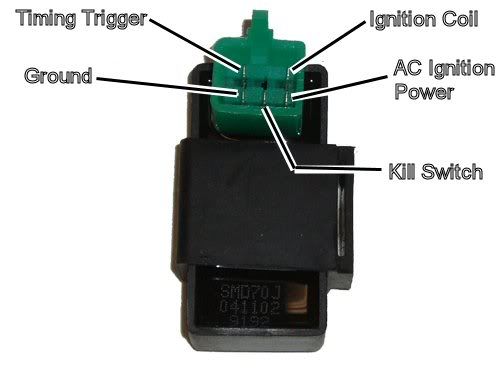
Here is the generic procedure for troubleshootng no spark on a 5 pin CDI:
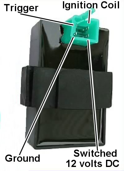
Is this a picture of your CDI?
Assuming the answer is yes, the first thing to do is eliminate all kill switches and kill switch wiring:
Method 1) Unplug the CDI and remove the kill switch pin in the CDI connector on the wiring harness. The pin is held in with a spring tab on the pin itself. You'll have to probe into the connector and push this tab in order to extract the pin. Plug the CDI back in (kill switch wire dangling) and see if you have spark.
Method 2) Unplug the CDI. Turn on the ignition switch and set all kill switches to the run position. Use a meter to measure resistance in of the kill switch pin in the wiring harness connector to engine/frame ground. If the resistance is infinite on the 200K ohm scale then your kill switches/kill switch wiring are OK. If you measure zero ohms then you have a kill switch/wiring issue.
The other inputs your CDI needs to make spark are AC Ignition Power, and the Trigger signal. Do the following:
1) Unplug the CDI. In the wiring connector measure the resistance of the AC Ignition Power pin to the Ground pin. You should see 400 ohms or so. What do you measure?
2) Measure the resistance of the Timing/trigger pin to the ground pin. You should measure 150 ohms or so. What do you measure?
3) Leave the CDI unplugged. Set your meter to measure AC volts on the 100 volt scale. Measure the voltage on the AC Ignition Power pin to the ground pin while cranking the engine. You should see 40 to 80 volts AC while the engine is cranking. What do you measure?
4) Set your meter to measure AC volts on the lowest scale you have. Ideally this would be 2 volts but many meters don't go down this low. In that case use the lowest scale you have. Measure the voltage on the Timing Trigger pin to the Ground pin while cranking the engine. You should 0.2 t0 0.4 volts AC. What do you measure?
Now for measuring the output side of the CDI:
A) Leave the CDI unplugged. In the CDI wiring connector measure the resistance of the Ignition Coil pin to the ground pin. You should measure less than 1 ohm (but not zero ohms). What do you measure?
B) Plug the CDI back in. Set your meter to measure AC volts on the 20 volt scale. Set all kill switches to the run position. Crank the engine while measuring the voltage on the Igntition Coil pin to ground. Poke through the insulation of the wire if you can't probe the connector.
Caution: There should be moderately high voltage spikes on this wire. Make sure your fingers are not part of the circuitry. Don't touch the probe lead tips while doing this test.
What you should see is a lot of random numbers with lots of zero values as well. This is because the meter may catch all or part of the spark event voltage, with a lot of nothing in between. Describe what you see.
Note: Using a meter to measure this point produces highly variable results depending on the meter. What you really need is an oscilloscope, but most always a meter is all that is available. We have to do the best we can with what's available. Describe the meter results as accurately as you can - there is information there to chew on....
Jun 19, 2012 | 12:18 AM
#6
Electrical Expert
Likes High Voltage In The Tub!
Likes High Voltage In The Tub!
Joined: Dec 2008
Posts: 3,260
Likes: 14
From: Tracy, California, USA
I waited on this to see from your other post (for another quad) to see what "no reading" means. So 'no reading' means open in this case, You're reporting 'open" for both the trigger and AC ignition power windings. Both are incorrect, and it seems unlikely that both would fail simultaneously. You reported 32.8 (ohms?) for a second, then it went open. That's wrong too.
Then in test #3 you report 48.2 volts AC on a wire you said was open. This is simply not possible. You're doing something very wrong. I don't know what because I'm not there. You're going to need to be a detective and sleuth this out. WHen you redo the measurement make sure you get the same readings each time. Report where you put the meter probes, and what the meter is set to (Volts/Ohms/AC/DC, and especially the scale). Give me as much info as possible. I'm trying to get clues as to what you are doing wrong...
I wonder if your meter is working. Maybe you have intermittent broken wires in the meter leads? Set you meter to measure ohms, then short the leads together. Wiggle the wires around (especially at the meter connectors and at the probes) to see if you read intermittent open circuit.
Jun 19, 2012 | 10:35 AM
#7

Thread Starter
|
Weekend Warrior
Joined: Jun 2012
Posts: 18
Likes: 0
1. 373 I was measuring on 200 scale not 2k thats why it was open
2. open tested on 200 and 2k ohm scale
3. 48.2 tested on 200 vac scale
4. .1 tested on 200 vac scale
A. .9 tested on 200 ohm scale
B. 0 tested on 200 vac scale
Meter is fairly new and is working properly
2. open tested on 200 and 2k ohm scale
3. 48.2 tested on 200 vac scale
4. .1 tested on 200 vac scale
A. .9 tested on 200 ohm scale
B. 0 tested on 200 vac scale
Meter is fairly new and is working properly
Trending Topics
Jun 20, 2012 | 12:01 AM
#8
Electrical Expert
Likes High Voltage In The Tub!
Likes High Voltage In The Tub!
Joined: Dec 2008
Posts: 3,260
Likes: 14
From: Tracy, California, USA
My comments in blue:
1. 373 I was measuring on 200 scale not 2k thats why it was open [Excellent - we are getting somewhere now  ]
]
2. open tested on 200 and 2k ohm scale [Big red flag... This is wrong. This is a problem.]
3. 48.2 tested on 200 vac scale [Good, and note how this agrees with 1) above. These two tests measure the same thing in different ways and harmoniously fit together.]
4. .1 tested on 200 vac scale [This should harmoniously fit together with #2 and it doesn't. Big red flag.]
A. .9 tested on 200 ohm scale [Looks good]
B. 0 tested on 200 vac scale [This is what would be expected if your trigger coil (test #2 and test #4) and working].
Look at the wire color for the trigger wire at the CDI connector and find that same wire down at the stator/wire harness connector. Unplug the stator connector and use you meter to do tests #2 and #4 again only this time measure the trigger wire looking into the stator. For ground (black meter lead) use the ground wire at the CDI connector, or engine ground, or the negative battery terminal. The readings you get should be the same for all these different grounds.
Does it still read open? If yes that your stator has a problem. If it reads 150 ohms or so then we have some wiring problems to figure out.
See the process? All this new test does is measure the same thing we did before but now right at the stator - which either will eliminate or point at the wiring. It's a divide and conquer process...
Meter is fairly new and is working properly
]2. open tested on 200 and 2k ohm scale [Big red flag... This is wrong. This is a problem.]
3. 48.2 tested on 200 vac scale [Good, and note how this agrees with 1) above. These two tests measure the same thing in different ways and harmoniously fit together.]
4. .1 tested on 200 vac scale [This should harmoniously fit together with #2 and it doesn't. Big red flag.]
A. .9 tested on 200 ohm scale [Looks good]
B. 0 tested on 200 vac scale [This is what would be expected if your trigger coil (test #2 and test #4) and working].
Look at the wire color for the trigger wire at the CDI connector and find that same wire down at the stator/wire harness connector. Unplug the stator connector and use you meter to do tests #2 and #4 again only this time measure the trigger wire looking into the stator. For ground (black meter lead) use the ground wire at the CDI connector, or engine ground, or the negative battery terminal. The readings you get should be the same for all these different grounds.
Does it still read open? If yes that your stator has a problem. If it reads 150 ohms or so then we have some wiring problems to figure out.
See the process? All this new test does is measure the same thing we did before but now right at the stator - which either will eliminate or point at the wiring. It's a divide and conquer process...
Meter is fairly new and is working properly
Jun 20, 2012 | 08:48 PM
#9
Thread Starter
|
Weekend Warrior
Joined: Jun 2012
Posts: 18
Likes: 0
tested at stator connector and same readings. Took the stator out and the pickup was busted and the windings where all over the place. put a stator from another 110 that i have and now i have spark. thank you for your patience and help.
