needing help with a hy bird 200cc n a vbike 250cc
#11
 07-16-2012, 10:11 AM


Join Date: Jul 2012
Posts: 8
Likes: 0
Received 0 Likes
on
0 Posts
#12
07-16-2012, 10:13 AM

Electrical Expert
Likes High Voltage In The Tub!
Likes High Voltage In The Tub!
Join Date: Dec 2008
Location: Tracy, California, USA
Posts: 3,260
Likes: 0
Received 13 Likes
on
13 Posts
Here are both the AC and DC testing procedures. I think the Vbike will be DC. I don't know about the hybird.
AC:
DC:
AC:
To troubleshoot no spark problems on a 6 pin AC powered CDI it makes sense to start in the middle (the CDI), measure as much as we can and branch out from there. For the CDI to do its thing it needs power, a trigger pulse, and it must must be inhibited via the kill switch input pin.
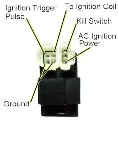
1) Unplug the CDI. Turn the ignition switch on. Set all kill switches the the "run" position. In the wiring harness, measure the resistance of the kill switch pin to the ground pin on the 20K ohm scale. It should read infinite ohms (same as when the meter leads are hanging free and not touching anything). It should not read zero ohms (shorted).
2) Leave the CDI unplugged. Use a meter to measure the resistance of the AC ignition power pin in the wiring harness to the ground wire on the 2K ohm scale. You should read approximately 400 ohms. What do you measure?
3) In a similar fashion measure the resistance of the Ignition Trigger Pulse pin to the ground pin. You should see 150 ohms or so. What do you measure?
4) Switch your meter over to measure AC volts on the 200 volt scale. Leave the CDI unplugged. While cranking the engine, measure the voltage on the AC Ignition Power pin in the wiring harness to the ground pin. You should measure 40 to 80 volts AC. What do you measure?
5) Set your meter down to the lowest scale you have for measuring AC volts. 2 volts would be ideal, but some meters don't go that low. In that case use the lowest scale you have. While cranking the engine, measure the voltage on the Ignition Trigger Pulse pin in the wiring harness to the ground pin. You should measure 0.2 to 0.5 volts AC. What do you measure?
6) Now plug the CDI back in. Measure the AC voltage on the Ignition Coil pin to the ground pin using the 200 volt scale. If you have to, use a sewing pin to poke through the wire insulation and then put the meter probe on the sewing pin. But don't hold your fingers on the connection during the next test - there may be high voltage here when the engine is turning. With the ignition on and all kill switches set to the "run" position, crank the starter motor. You should see voltages bouncing around at random values and the meter captures all or part of a spark event. What do you see?
To troubleshoot no spark problems on a 6 pin DC powered CDI it makes sense to start in the middle (the CDI), measure as much as we can and branch out from there. For the CDI to do its thing it needs power, a trigger pulse, and it must not be inhibited via the kill switch input pin.
1) Unplug the CDI. Turn the ignition switch on. Set all kill switches the the "run" position. In the wiring harness, look to see if you have a wire on the kill switch pin. If you do, measure the resistance of the kill switch pin to the ground pin on the 20K ohm scale. It should read infinite ohms (same as when the meter leads are hanging free and not touching anything). It should not read zero ohms (shorted).
2) Leave the CDI unplugged. Turn off the ignition switch. Set your meter to the lowest resistance scale you have (like 2 ohms or 20 ohms full scale). Measure the resistance of the "Ignition Coil" pin in the wiring harness to the ground pin. You should read something around 0.7 ohms (but not zero ohms). What do your measure?
3) Leave the CDI unplugged and the ignition switch off. Set your meter to the lowest resistance scale you have (like 2 ohms or 20 ohms full scale). Measure the resistance of the "Ground" pin in the wiring harness to the the negative battery terminal. You should read zero ohms. What do your measure?
4) Leave the CDI unplugged, and turn the ignition switch into the "on" position. Use a meter to measure the DC voltage on the pin labeled "AC ignition power" in the wiring harness to the ground wire on the 20 volt DC scale. You should read battery voltage (12 volts). What do you measure?
5) Leave the CDI unplugged. Use a meter to measure the resistance of the "Ignition Trigger Pulse" pin in the wiring harness to the ground wire on the 2K ohm scale. You should read approximately 150 ohms. What do you measure?
6) Set your meter down to the lowest scale you have for measuring AC volts. 2 volts would be ideal, but some meters don't go that low. In that case use the lowest scale you have. While cranking the engine, measure the voltage on the Ignition Trigger Pulse pin in the wiring harness to the ground pin. You should measure 0.2 to 0.5 volts AC. What do you measure?
7) Now plug the CDI back in. Measure the AC voltage on the Ignition Coil pin to the ground pin using the 200 volt scale. If you have to, use a sewing pin to poke through the wire insulation and then put the meter probe on the sewing pin. But don't hold your fingers on the connection during the next test - there may be high voltage here when the engine is turning. With the ignition on and all kill switches set to the "run" position, crank the starter motor. You should see voltages bouncing around at random values and the meter captures all or part of a spark event. What do you see?
#14
07-16-2012, 10:20 AM
Join Date: Jul 2012
Posts: 8
Likes: 0
Received 0 Likes
on
0 Posts

Thread
Thread Starter
Forum
Replies
Last Post
Currently Active Users Viewing This Thread: 1 (0 members and 1 guests)