
2006 Buyang FA-C70 Wiring Help Needed
 Nov 17, 2012 | 02:12 PM
#1

Thread Starter
|
Weekend Warrior
Joined: Nov 2012
Posts: 3
Likes: 0
I picked up a Buyang FA-C70 ATV for my Grand Daughter but the guy who had it said it quit running and tried to fix it but in the process butchered the wiring harness, I would just like to make a basic wiring harness to get it running for her, in no need of light's or other fancy stuff just start run and off.
I have so far made up a starter switch and have engine turning over now have to figure out the rest of the mess need to make it as simple as possible.
1/ coil has besides the obvious plug wire a green for ground and a black wire with white stripe.
2/ guessing a 4 pin box is a voltage regulator with yellow,white, green and a black wire. green and white go to stater green is ground? black wire no idea.
3/ wires from stater yellow, white, (going to Reg box) blue with white stripe no idea just cut off and hanging, black with red stripe no idea just cut and hanging.
If there was to be a CDI box there isn't one nor is there any other wires to support it that I can see.
Any help would be greatly appreciated as to get my 7yr old Grand daughter off my back!.
Tnx
Tim Wetzel
Nov 17, 2012 | 07:32 PM
#2

Electrical Expert
Likes High Voltage In The Tub!
Likes High Voltage In The Tub!
Joined: Dec 2008
Posts: 3,260
Likes: 14
From: Tracy, California, USA
My comments embedded in blue:
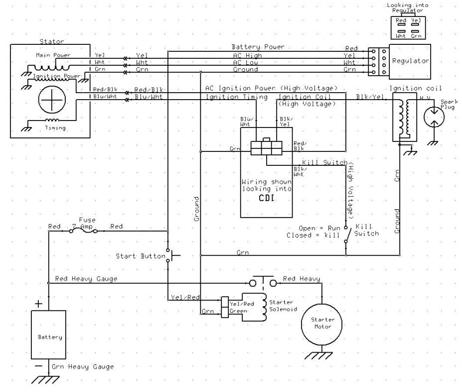
Study the diagram below and see if it makes any sense to you. Then come back with questions. Keep in mind that this is a "bare bones" diagram. The starter motor safety interlock (which won't let you crank the starter motor unless the brakes are applied) has been removed. With the diagram below there is nothing to prevent your grand daughter from starting up the quad in gear and take off unexpectedly.
Also, your quad was having problems before. That problem may still exist, so be prepared to do some testing with a meter before this project is over.

I picked up a Buyang FA-C70 ATV for my Grand Daughter but the guy who had it said it quit running and tried to fix it but in the process butchered the wiring harness, I would just like to make a basic wiring harness to get it running for her, in no need of light's or other fancy stuff just start run and off. [Below I've attached a bare bones wiring diagram for 110cc quads which in all likelyhood will work on your quad. Click or hover over the thumbnail to get an expanded picture.]
I have so far made up a starter switch and have engine turning over now have to figure out the rest of the mess need to make it as simple as possible. [You're using the starter solenoid to switch the starter motor current (about 30 amps) I hope. ]
1/ coil has besides the obvious plug wire a green for ground and a black wire with white stripe. [ARe you sure it is not black/yellow? Black/white is almost always a kill switch wire. Do you have any kill switches on the quad? That would include the handlebar kill switch, one half of the ignition switch, and a tether pull cord. In any case the ignition coil primary is driven from the CDI, which you will need to buy. You need a five wire AC powered CDI.]
2/ guessing a 4 pin box is a voltage regulator with yellow,white, green and a black wire. green and white go to stater green is ground? black wire no idea. [Green, White, and Yellow should all go to the stator. Black is a common color for switched 12 volts DC. Again, do you have an ignition switch?]
3/ wires from stater yellow, white, (going to Reg box) blue with white stripe no idea just cut off and hanging, black with red stripe no idea just cut and hanging. [Blue/white is a classic color for the ignition timing wire. It goes from the stator to the CDI. Black/red is a classic color fro the moderately high voltage AC ignition power. It goes from the stator to the CDI.]
If there was to be a CDI box there isn't one nor is there any other wires to support it that I can see. [Well two of the five wires that go to your CDI are the dangling blue/white and black/red wires above. Another is the wire to your ignition coil. The other two are ground (green) and the kill switch (black/white).]
Any help would be greatly appreciated as to get my 7yr old Grand daughter off my back!.
Tnx
Tim Wetzel
Also, your quad was having problems before. That problem may still exist, so be prepared to do some testing with a meter before this project is over.
 Nov 17, 2012 | 07:43 PM
#3
Electrical Expert
Likes High Voltage In The Tub!
Likes High Voltage In The Tub!
Joined: Dec 2008
Posts: 3,260
Likes: 14
From: Tracy, California, USA
One more question: Do you have an automatic choke? In other words, so you have wires going to your carburetor?
Also, if you want to get a head start, do all of the tests that you can in the generic procedure below. That will partially test your stator and ignition coil. The procedure asks you to measure voltages and resistances from the CDI pins, which you don't have. But if you look at the wiring diagram in the last post you can see where they go. So measure the resistances and voltage there instead. For example, the procedure asks you measure the AC Ignition Power pin on the CDI wiring harness to ground. You don't have that connector, so move on down to the black/red wire on the stator and do the test there (which is where the CDI pin would go if you had one).
Also, if you want to get a head start, do all of the tests that you can in the generic procedure below. That will partially test your stator and ignition coil. The procedure asks you to measure voltages and resistances from the CDI pins, which you don't have. But if you look at the wiring diagram in the last post you can see where they go. So measure the resistances and voltage there instead. For example, the procedure asks you measure the AC Ignition Power pin on the CDI wiring harness to ground. You don't have that connector, so move on down to the black/red wire on the stator and do the test there (which is where the CDI pin would go if you had one).
Is this a picture of your CDI?
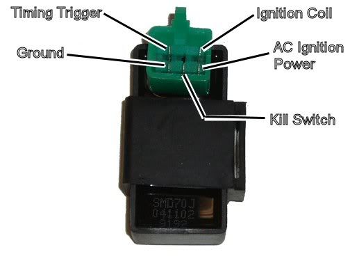
Assuming the answer is yes, the first thing to do is eliminate all kill switches and kill switch wiring:
Method 1) Unplug the CDI and remove the kill switch pin in the CDI connector on the wiring harness. The pin is held in with a spring tab on the pin itself. You'll have to probe into the connector and push this tab in order to extract the pin. Plug the CDI back in (kill switch wire dangling) and see if you have spark.
Method 2) Unplug the CDI. Turn on the ignition switch and set all kill switches to the run position. Use a meter to measure resistance in of the kill switch pin in the wiring harness connector to engine/frame ground. If the reistance is infinite on the 100K ohm scale then your kill switches/kill switch wiring are OK. If you measure zero ohms then you have a kill switch/wiring issue.
The other inputs your CDI needs to make spark are AC Ignition Power, and the Trigger signal. Do the following:
1) Unplug the CDI. In the wiring connector measure the resistance of the AC Ignition Power pin to the Ground pin. You should see 400 ohms or so. What do you measure?
2) Measure the resistance of the Timing/trigger pin to the ground pin. You should measure 150 ohms or so. What do you measure?
3) Leave the CDI unplugged. Set your meter to measure AC volts on the 100 volt scale. Measure the voltage on the AC Ignition Power pin to the ground pin while cranking the engine. You should see 40 to 80 volts AC while the engine is cranking. What do you measure?
4) Set your meter to measure AC volts on the lowest scale you have. Ideally this would be 2 volts but many meters don't go down this low. In that case use the lowest scale you have. Measure the voltage on the Timing Trigger pin to the Ground pin while cranking the engine. You should 0.2 t0 0.4 volts AC. What do you measure?
Now for measuring the output side of the CDI:
A) Leave the CDI unplugged. In the CDI wiring connector measure the resistance of the Ignition Coil pin to the ground pin. You should measure less than 1 ohm (but not zero ohms). What do you measure?
B) Plug the CDI back in. Set your meter to measure AC volts on the 20 volt scale. Set all kill switches to the run position. Crank the engine while measuring the voltage on the Igntition Coil pin to ground. Poke through the insulation of the wire if you can't probe the connector.
Caution: There should be moderately high voltage spikes on this wire. Make sure your fingers are not part of the circuitry. Don't touch the probe lead tips while doing this test.
What you should see is a lot of random numbers with lots of zero values as well. This is because the meter may catch all or part of the spark event voltage, with a lot of nothing in between. Describe what you see.
Note: Using a meter to measure this point produces highly variable results depending on the meter. What you really need is an oscilloscope, but most always a meter is all that is available. We have to do the best we can with what's available. Describe the meter results as accurately as you can - there is information there to chew on....
Nov 18, 2012 | 09:19 AM
#5
Thread Starter
|
Weekend Warrior
Joined: Nov 2012
Posts: 3
Likes: 0
Yep makes sense, the missing link was the CDI box guy striped all wiring off the ATV so no handle bar starter button or kill switch ect just the wire's that I had listed, I had a boat starter switch with 3 terminals Batt, Ing, Sole, and nope the wire is not yellow and black, it is as stated black with white stripe, diagram looks good just need to get a CDI box then go from there and see what happens.
Tnx so much you have been a great help.
Tim
Tnx so much you have been a great help.
Tim
Nov 3, 2020 | 01:32 AM
#7

Weekend Warrior
Joined: Nov 2020
Posts: 1
Likes: 0
One more question: Do you have an automatic choke? In other words, so you have wires going to your carburetor?
Also, if you want to get a head start, do all of the tests that you can in the generic procedure below. That will partially test your stator and ignition coil. The procedure asks you to measure voltages and resistances from the CDI pins, which you don't have. But if you look at the wiring diagram in the last post you can see where they go. So measure the resistances and voltage there instead. For example, the procedure asks you measure the AC Ignition Power pin on the CDI wiring harness to ground. You don't have that connector, so move on down to the black/red wire on the stator and do the test there (which is where the CDI pin would go if you had one).
Also, if you want to get a head start, do all of the tests that you can in the generic procedure below. That will partially test your stator and ignition coil. The procedure asks you to measure voltages and resistances from the CDI pins, which you don't have. But if you look at the wiring diagram in the last post you can see where they go. So measure the resistances and voltage there instead. For example, the procedure asks you measure the AC Ignition Power pin on the CDI wiring harness to ground. You don't have that connector, so move on down to the black/red wire on the stator and do the test there (which is where the CDI pin would go if you had one).
Trending Topics
Nov 3, 2020 | 02:10 AM
#8

Elite Pro Rider


Joined: Oct 2013
Posts: 7,483
Likes: 387
From: Lancaster England
Sorry, but you are all over the place.
Point 1. Quadsport LT80s are made by Suzuki and have an unusual ignition system, early ones don't even have a CDI box. It would be difficult to fit any other engine as the engine doubles as the swinging arm. However Kazuma made a bike using a Honda clone engine and Suzuki LT80 plastics, are you sure this isn't what you have? Stickers mean nothing on any used Quad.
Point 2. If it has "milky oil" on an air cooled engine, this has nothing to do with the head gasket.
Point 3. Making a head gasket is risky, only to be done if gaskets are unavailable. If your engine is the usual 70cc Honda clone, head gaskets are available from eBay very cheap.

Thread
Thread Starter
Forum
Replies
Last Post
jrooker6
Ask the Editor
11
Apr 21, 2016 07:35 PM
Daryl Devine
Technical and How-To Articles
1
Jun 8, 2015 08:59 AM
Currently Active Users Viewing This Thread: 1 (0 members and 1 guests)

