
New CDI...
#51
 07-04-2012, 02:11 AM


Electrical Expert
Likes High Voltage In The Tub!
Likes High Voltage In The Tub!
Join Date: Dec 2008
Location: Tracy, California, USA
Posts: 3,260
Likes: 0
Received 13 Likes
on
13 Posts
You have two coils spaced 180 degrees apart. You cannot get there from here.
#53
07-06-2012, 08:46 PM
Electrical Expert
Likes High Voltage In The Tub!
Likes High Voltage In The Tub!
Join Date: Dec 2008
Location: Tracy, California, USA
Posts: 3,260
Likes: 0
Received 13 Likes
on
13 Posts
I don't know what you mean by an "online converter".
If you take any AC voltage, rectify it (using diodes), and store it on a capacitor, and if this rectified/stored output voltage is *unloaded*, the DC voltage will climp to the "peak" AC voltage minus any voltage drop across the rectifying diodes.
For an AC sine wave (and the unloaded AC voltage output from the stator is pretty close to a sine wave), the peak voltage is the RMS voltage (what your meter says) times the square root of two (approximately 1.4). So a 10 volt AC signal will rectify to about 1.4 times that or 14 volts DC (unloaded).
If you're wondering why or how AC voltage is determined (in other words how can you assign a constant voltage to a voltage that in reality is varying all over the place), it all has to do with *power* (which is the rate at which energy is consumed).
Consider a 10 volt DC power source that is driving a 10 ohm resistor. The current (using ohms law) will be one amp and the power dissipated as heat in the resistor will be the voltage times the current, or 10 watts. That 10 watts of power in the resistor is going to go up entirely up as generated heat. So if we measure the temperature rise of that resistor we get an indication of what ten watts will generate in heat for that setup.
Now put an AC voltage sine wave across the same resistor and measure the heat rise. If we adjust the AC voltage such that we are dissipating the same power (in other words the same heat rise on the same setup) we define that AC voltage as 10 volts AC. Of course the maximum (peak) voltage will have to have a higher to make up for the fact that the voltage is often much less than 10 volts. For a sine wave only the AC voltage will be the peak voltage multiplied by (root 2 over 2), or 0.707. For any other waveforms other than sine waves you'd better be really good at calculus.
But all this aside, the output voltage of the stator also varies with load. That's another variable to contend with. Again this makes it extremely difficult to model when maximum power conversion efficiency is your goal. Trial and error, followed by converging approximation based on your measured results is the only way forward.
#54
07-08-2012, 12:54 AM
#55
07-08-2012, 02:44 AM
My ignition coil is a little rusted on the contacts, so I was going to replace it. Will a coil like this work: http://item.mobileweb.ebay.com/viewi...d=120938130268
I might be a little crazy, but I didn't want a generic coil so I looked at some full sized ones. Also the stator holds up well at idle with one coil (when the headlights are on) but I'm going to buy a second coil. Oh one more thing, is a mechanical brake switch better than a hydrulic switch?
I might be a little crazy, but I didn't want a generic coil so I looked at some full sized ones. Also the stator holds up well at idle with one coil (when the headlights are on) but I'm going to buy a second coil. Oh one more thing, is a mechanical brake switch better than a hydrulic switch?
#56
07-09-2012, 11:10 PM
Electrical Expert
Likes High Voltage In The Tub!
Likes High Voltage In The Tub!
Join Date: Dec 2008
Location: Tracy, California, USA
Posts: 3,260
Likes: 0
Received 13 Likes
on
13 Posts
Fuses are much cheaper. That's what I would use. Circuit breakers have the advantage of being resettable, but so what? You shouldn't be blowing fuses on a regular basis...
If you full wave rectify an AC waveform and then take the *average* voltage you get 0.636 times the *peak* input voltage. But your meter measures RMS voltages not peak, and in power supply design we are not concerned with average voltages at all. Your online calculator is correct, but not applicable to the questions at hand... 
Chinese regulators are copies of Honda regulators. How well do they work? It depends on how well they were copied, as well as how well they were assembled. You can rest assured they don't spend more then 5 seconds testing them. That can be a problem, or not. The performance varies all over the place depending on the source and the batch. You take your chances, but the price difference is so great that many think the risk is worth it.
Also note there are *many* different 4 pin regulators out there. Even though they look the same, and use the same connector, they are incompatible with each other. Your looking to use the GY6 version which has a bridge rectifier on the the two power input wires.
#57
07-09-2012, 11:18 PM
Electrical Expert
Likes High Voltage In The Tub!
Likes High Voltage In The Tub!
Join Date: Dec 2008
Location: Tracy, California, USA
Posts: 3,260
Likes: 0
Received 13 Likes
on
13 Posts
My ignition coil is a little rusted on the contacts, so I was going to replace it. Will a coil like this work: http://item.mobileweb.ebay.com/viewitem?itemId=120938130268
I might be a little crazy, but I didn't want a generic coil so I looked at some full sized ones....
I might be a little crazy, but I didn't want a generic coil so I looked at some full sized ones....
A switch is a switch. Either one. I'd stick with what you have.
#58
07-21-2012, 02:27 AM
#59
07-21-2012, 10:05 PM
Electrical Expert
Likes High Voltage In The Tub!
Likes High Voltage In The Tub!
Join Date: Dec 2008
Location: Tracy, California, USA
Posts: 3,260
Likes: 0
Received 13 Likes
on
13 Posts
Yes, it is just a rectifier and a regulator, but don't under estimate power dissipation in the regulator. If your thinking of a linear regulator scheme, this absolutely will not work. It would have to be water cooled, and remember you're trying to maximize power delived to the load(s) - not consume it all in heat at the regulator.
Rather than reinvent the wheel, why not take advantage of the knowledge base already out there? Here is a real, working, and *efficient* GY6 style regulator diagram:
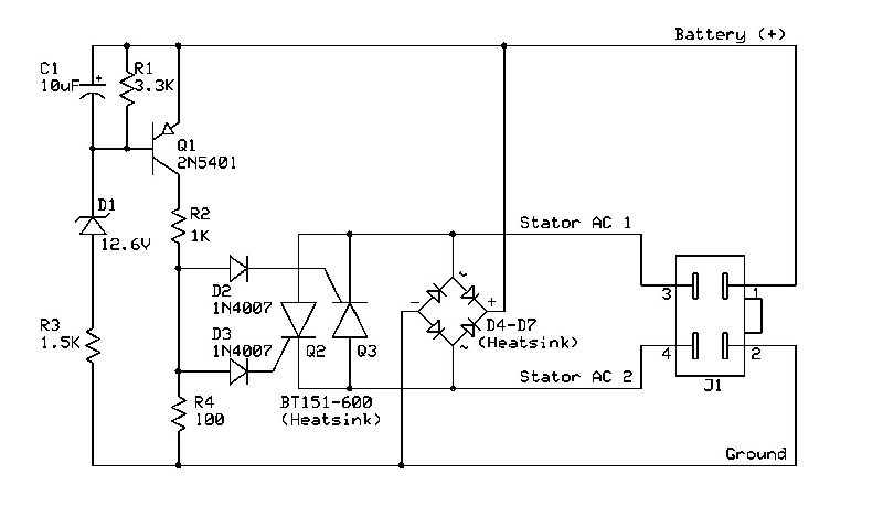
Do you see how it works? The bridge rectifier you'll probably recognize. What is not so obvious is the way the charging system limited by shorting out (yes shorting out) the stator charge winding when the battery charge voltage gets too high by SCR Q2 and Q3 . It stays shorted out for some portion of one engine revolution as required (and each subsequent revolution as well).
What is not intuitive is that the stator output is inherently current limited, and this is a completely legitimate way to limit charging voltage without dissipating any power in the stator or the regulator. It also doesn't subtract from the engine horsepower.
Rather than reinvent the wheel, why not take advantage of the knowledge base already out there? Here is a real, working, and *efficient* GY6 style regulator diagram:
Do you see how it works? The bridge rectifier you'll probably recognize. What is not so obvious is the way the charging system limited by shorting out (yes shorting out) the stator charge winding when the battery charge voltage gets too high by SCR Q2 and Q3 . It stays shorted out for some portion of one engine revolution as required (and each subsequent revolution as well).
What is not intuitive is that the stator output is inherently current limited, and this is a completely legitimate way to limit charging voltage without dissipating any power in the stator or the regulator. It also doesn't subtract from the engine horsepower.
#60
07-23-2012, 12:35 AM
I will probably follow that diagram. Will a plastic project box hold it (the ones at RadioShack)? I think I'm going to need a heatsink type box instead. I've heard about MOSFET regulators and switching ones, are those any better? And would I be able to build that? Also, how do stators subtract from horsepower? And how is the stator output "inherently current limited"? Sorry for all of the questions...