
New CDI...
#1
 06-13-2012, 10:19 PM

Hello,
I got a new gold (6 pin) Casoli DC CDI, my ATV originally was AC ignition powered. I ripped out the old wiring harness (it was showing age) completely and was wondering how to install this CDI...
Here is the Ebay link: New Casoli DC CDI Performance Racing for GY6 150cc 250cc ATV/Go kart/Quad bike | eBay
#2
06-13-2012, 11:46 PM

Electrical Expert
Likes High Voltage In The Tub!
Likes High Voltage In The Tub!
Join Date: Dec 2008
Location: Tracy, California, USA
Posts: 3,260
Likes: 0
Received 13 Likes
on
13 Posts
I'm wondering why you didn't buy an AC powered performance CDI...
I'm especially wondering why you ripped out the entire wiring harness...
What are you going to do to replace it? That's a really big job... Even if you want to eliminate all that "useless stuff" (I hear this a lot) like safety interlocks and lights, there is still the "absolutely required stuff" like starting circuitry, the entire ignition system, the battery charging circuitry, ignition kill ciruitry, and automatic choke wiring (if you have that). That's a lot of wires . Are you sure you're up to this? Lots of people have gone down this route before you. To date *none* have got past the first step where they got the starter motor cranking with a push button. That's just a teeny baby step in the grand scheme of things that you're going to need to tackle...
I'm especially wondering why you ripped out the entire wiring harness...
What are you going to do to replace it? That's a really big job... Even if you want to eliminate all that "useless stuff" (I hear this a lot) like safety interlocks and lights, there is still the "absolutely required stuff" like starting circuitry, the entire ignition system, the battery charging circuitry, ignition kill ciruitry, and automatic choke wiring (if you have that). That's a lot of wires
. Are you sure you're up to this? Lots of people have gone down this route before you. To date *none* have got past the first step where they got the starter motor cranking with a push button. That's just a teeny baby step in the grand scheme of things that you're going to need to tackle...
Last edited by LynnEdwards; 06-13-2012 at 11:55 PM. Reason: Clarification
#3
06-14-2012, 09:21 AM
#4
06-14-2012, 11:41 PM
Electrical Expert
Likes High Voltage In The Tub!
Likes High Voltage In The Tub!
Join Date: Dec 2008
Location: Tracy, California, USA
Posts: 3,260
Likes: 0
Received 13 Likes
on
13 Posts
So here is how it is wired:
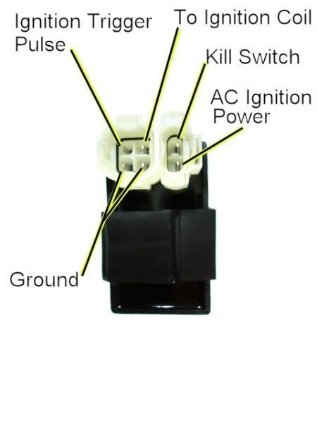
Only change the pin labled AC Ignition Power to read Switched Fused 12 Volts.
I'm wondering about the statement:
This has me confused. Stators are always outputting AC voltage and never DC. It cannot be any other way. To generate a voltage in a coil of wire you need to have a moving magnetic field, and a moving magnetic field generates a moving voltage (i.e. AC voltage). That's just the way the physics works.
To convert to DC you need to take the AC output from the stator and rectify it with diodes (which only let current pass one way) into DC. It is also conceivably possible to rectify it in other ways - like the old "generators" in cars back in the early nineteen sixties. They used mechanical rectifiers (they called them commutators) but they were rectifiers none the less. ANd they faded out of existance back then because it was a poorer performer compared to alternators using diodes fro a rectifier.
Only change the pin labled AC Ignition Power to read Switched Fused 12 Volts.
I'm wondering about the statement:
because I was making the stator to be pure DC to possibly give more power
To convert to DC you need to take the AC output from the stator and rectify it with diodes (which only let current pass one way) into DC. It is also conceivably possible to rectify it in other ways - like the old "generators" in cars back in the early nineteen sixties. They used mechanical rectifiers (they called them commutators) but they were rectifiers none the less. ANd they faded out of existance back then because it was a poorer performer compared to alternators using diodes fro a rectifier.
#5
06-15-2012, 01:18 AM
So here is how it is wired:
Only change the pin labled AC Ignition Power to read Switched Fused 12 Volts.
I'm wondering about the statement: This has me confused. Stators are always outputting AC voltage and never DC. It cannot be any other way. To generate a voltage in a coil of wire you need to have a moving magnetic field, and a moving magnetic field generates a moving voltage (i.e. AC voltage). That's just the way the physics works.
To convert to DC you need to take the AC output from the stator and rectify it with diodes (which only let current pass one way) into DC. It is also conceivably possible to rectify it in other ways - like the old "generators" in cars back in the early nineteen sixties. They used mechanical rectifiers (they called them commutators) but they were rectifiers none the less. ANd they faded out of existance back then because it was a poorer performer compared to alternators using diodes fro a rectifier.
#6
06-15-2012, 11:45 PM
Electrical Expert
Likes High Voltage In The Tub!
Likes High Voltage In The Tub!
Join Date: Dec 2008
Location: Tracy, California, USA
Posts: 3,260
Likes: 0
Received 13 Likes
on
13 Posts

That's true. When you free up that extra pole formally used to power the CDI it can be used to generate more power for the 12 volt bus through the voltage regulator. But the increase in power will be much smaller than you think. Here's why:
Once you add that extra pole in the stator onto the 12 volt charging bus your AC CDI isn't powered anymore. So your new DC CDI is powered how? By hooking it onto the 12 volt bus and loading it down - taking a big chunk back out of the increase you just added.
On my GY6 150cc 8 pole stator (7 poles for the battery charging system and one for the ignition) I can get 55 watts out of the stator. It seems reasonable to assume that I can get 8/7'ths as much power to the 12 volt bus if I go with dedicating all eight poles to the task. That would give me 63 watts maximum, or an increase of eight watts.
I've never measured how much power a CDI uses. I'm going to go out on a limb using back of the envelope calculations (and subject to calculation error and correction). I calculate that at 3000 RPM the CDI will transfer 3.3 watts of power to the ignition coil. That's delivered power through the CDI and doesn't include any power dissipated by the CDI itself. Assuming overall transfer efficiency of 70% that means the total consumption would be 4.7 watts (meaning 1.4 watts go up as heat in the CDI). So that leaves you 3.3 watts ahead by switching to a DC powered CDI. 3.3 watts gives about 0.3 amps of increased reserve current capacity at 3000 RPM.
A 250cc three phase charging system may do much better. I've never measured the output capacity of one of these. It may well be the increase in output capacity is significant. I don't know.
On some quads the pickup coil has two wires coming out of it. One of those gets grounded at the CDI, and the other is the signal that triggers the CDI. By grounding the return wire at the CDI (instead of at the stator) there is an increase in noise immunity (i.e. false triggers caused by transient voltages coupled from adjacent wires). Again you still need another good ground from the CDI to the engine or frame somewhere in addition to the trigger return wire. This is why the 6 pin CDI has two ground pins. Depending on your wiring scenario you either use both pins or you don't.
#7
06-16-2012, 03:23 AM
Trending Topics
#9
06-16-2012, 11:42 PM
No, I mean my pick up coil has 2 wires. One is green and one is blue, I want to connect the pickup coil straight to the CDI for better signal. So there are two green wires on the CDI, which one goes to the pick up coil directly?
#10
06-17-2012, 01:29 AM
Electrical Expert
Likes High Voltage In The Tub!
Likes High Voltage In The Tub!
Join Date: Dec 2008
Location: Tracy, California, USA
Posts: 3,260
Likes: 0
Received 13 Likes
on
13 Posts
I bet if you take an ohmmeter and measure your actual CDI you'll find those two ground pins looking into the CDI are connected together. If that's the case (as it has been with every 6 pin CDI I've taken apart) then it doesn't matter which ground pin you use - they are the same point at the CDI internal printed circuit board.