
Stator Wire Colors Issue
 Jun 29, 2012 | 09:41 PM
#1

Thread Starter
|
Weekend Warrior
Joined: Jun 2012
Posts: 4
Likes: 0
We have a 250 Tao Tao and the chain caught the wires on the stator and split them. The wires on the stator are 1 red/wht; 2 wht; 1 blk/red; and 1 Blk
but the ones coming off the quad are blue/wht; grn; pnk/blk; yellow; and wht.
Which wires hook up to each other.
Thank you for any help.
but the ones coming off the quad are blue/wht; grn; pnk/blk; yellow; and wht.
Which wires hook up to each other.
Thank you for any help.
Jun 30, 2012 | 12:06 AM
#2

Electrical Expert
Likes High Voltage In The Tub!
Likes High Voltage In The Tub!
Joined: Dec 2008
Posts: 3,260
Likes: 14
From: Tracy, California, USA
Look at your CDI. Does it look like this?
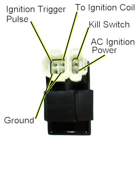
If so, look at the colors connecting to each pin and report what color wire in your harness ties to each pin. For example, What color ties to the "AC Ignition POwer" pin, etc. Several of those same colors will appear down at the stator end of the harness, and that will help me figure out how to wire up to your stator.
If so, look at the colors connecting to each pin and report what color wire in your harness ties to each pin. For example, What color ties to the "AC Ignition POwer" pin, etc. Several of those same colors will appear down at the stator end of the harness, and that will help me figure out how to wire up to your stator.
Jun 30, 2012 | 09:26 PM
#4
Electrical Expert
Likes High Voltage In The Tub!
Likes High Voltage In The Tub!
Joined: Dec 2008
Posts: 3,260
Likes: 14
From: Tracy, California, USA
But the colors at your stator side don't match up. Theere is some confusion here so let's clear it up
 :
:When you said:
The wires on the stator are 1 red/wht; 2 wht; 1 blk/red; and 1 Blk but the ones coming off the quad are blue/wht; grn; pnk/blk; yellow; and wht.
2) Are you sure the pnk/blk wire is not blk/red?
3) Unplug the stator wires (coming out of the engine) from the wiring harness. Get a meter and set it to measure resistance on the 2000 ohm scale (2K ohm). Measure the resistance of all 5 wires to the negative battery terminal. What do you measure for:
a) Red/Wht
b) Wht #1
c) Wht #2
d) Blk/Red
e) Blk
We will get this straightened out. We just need to clean up a few descrepancies first...
 Jul 1, 2012 | 04:26 PM
#5
Thread Starter
|
Weekend Warrior
Joined: Jun 2012
Posts: 4
Likes: 0
The ones coming out of the engine do not match the harness that plug into the CDI.
When you check the resistance from any of the wires to the neg terminal.
The quad ran before the change tore the harness into 2 pieces...
When you check the resistance from any of the wires to the neg terminal.
The quad ran before the change tore the harness into 2 pieces...
Jul 1, 2012 | 10:50 PM
#6
Electrical Expert
Likes High Voltage In The Tub!
Likes High Voltage In The Tub!
Joined: Dec 2008
Posts: 3,260
Likes: 14
From: Tracy, California, USA
My comments in blue...
The ones coming out of the engine do not match the harness that plug into the CDI. [Yes I know this. We're not communicating (partially my fault). In your original post you said the
These are somewhat standard colors except for the red/wht. And I interpretted that as meaning the wires coming out of the engine (the stator). Further you said:
These wires I interpretted and coming from the wire harness. Some of these wire go to the CDI. The pink/blk wire is *not* a standard color. The rest are. But you wire colors at the CDI are:
These are *all* standard colors - and they don't match completely the wires at the stator, or the stator connector. Thus I need more info. ]
When you check the resistance from any of the wires to the neg terminal. [I'm interested in the resistance of all the wires (in ohms) from each wire coming out of the stator (from the engine side cover) to the negative battery terminal with the ignition switch off. These resistances will help me determine what wire is what from the stator. That will help me determine how to wire it up to the harness.
Do you have a meter? When you make measurements be sure to tell me eveything the meter says. What scale setting? What Units (as in K ohms, M ohms, or just ohms)? Phrases such as "I got nothing" or "it all measured good" are very common (unfortunately) but not helpful at all
There is another discrepancy also. The pink/black wire doesn't add up. I'm asking again that you verify that. Make sure that is is not black/red. I'm not saying you're wrong - I'm just trying to make sure that a simple error doesn't send us down a dead end path. Accuracy is paramount, and part of the troubleshooting process is to constantly verify what you measure to be sure that it is repeatable and consistent. It is so easy to make a measurent mistake - as I can say from decades of personal experinence. Verify, verify, and verify again...]
The quad ran before the change tore the harness into 2 pieces [I totally believe you...]...
...The wires on the stator are 1 red/wht; 2 wht; 1 blk/red; and 1 Blk...
These are somewhat standard colors except for the red/wht. And I interpretted that as meaning the wires coming out of the engine (the stator). Further you said:
...but the ones coming off the quad are blue/wht; grn; pnk/blk; yellow; and wht...
These wires I interpretted and coming from the wire harness. Some of these wire go to the CDI. The pink/blk wire is *not* a standard color. The rest are. But you wire colors at the CDI are:
Ignition Trigger-blue wht
To Coil-blk/yellow
Ground-green
Kill Switch-blk/wht
AC Ignition-red/blk
Ground-green
Kill Switch-blk/wht
AC Ignition-red/blk
]When you check the resistance from any of the wires to the neg terminal. [I'm interested in the resistance of all the wires (in ohms) from each wire coming out of the stator (from the engine side cover) to the negative battery terminal with the ignition switch off. These resistances will help me determine what wire is what from the stator. That will help me determine how to wire it up to the harness.
Do you have a meter? When you make measurements be sure to tell me eveything the meter says. What scale setting? What Units (as in K ohms, M ohms, or just ohms)? Phrases such as "I got nothing" or "it all measured good" are very common (unfortunately) but not helpful at all
There is another discrepancy also. The pink/black wire doesn't add up. I'm asking again that you verify that. Make sure that is is not black/red. I'm not saying you're wrong - I'm just trying to make sure that a simple error doesn't send us down a dead end path. Accuracy is paramount, and part of the troubleshooting process is to constantly verify what you measure to be sure that it is repeatable and consistent. It is so easy to make a measurent mistake - as I can say from decades of personal experinence
. Verify, verify, and verify again...]The quad ran before the change tore the harness into 2 pieces [I totally believe you...]...
Jul 1, 2012 | 10:58 PM
#7
Thread Starter
|
Weekend Warrior
Joined: Jun 2012
Posts: 4
Likes: 0
The wire that I said had pink is indeed blk/red...it was dark When I was checking SORRY...
We actually used 2 multi meters, we had one that you can just set to ohms and it read just like the other that was set at 2000 like you said to. No wire gave any resistance reading.
(Both my husband (Current he still does) and I worked on electronics on helicopters for the Army) and this quad is kicking our butt. I appreciate any and all the help you are giving us.
Trending Topics
Jul 4, 2012 | 01:44 AM
#8
Electrical Expert
Likes High Voltage In The Tub!
Likes High Voltage In The Tub!
Joined: Dec 2008
Posts: 3,260
Likes: 14
From: Tracy, California, USA
Sorry for the delay in responding. I'm really behind in my posts, and somewhat disorganized too. I haven't been following the first in first out rule too well...
If you're sure about the open connections looking into the stator then the sheared wires must have tugged apart solder connections inside the stator. Have you remove the engine cover over the stator and looked inside? Do you see anything amiss?
Also as a verification can you look at the resistance between all the wires going into the stator (lokking into the engine side cover). You stated that no wire has any connection to ground (the negative battery post). But does any wire from the stator hook to any other wire? They should. Use the 2000 ohm scale like you did before.
Feb 17, 2022 | 08:01 AM
#9

Weekend Warrior
Joined: Feb 2022
Posts: 1
Likes: 0
So, I'm trying to use this place as a resource to resolve issues too.
But none of yall Ever Actually put enough information to do anything with. Yall quickly get distracted and off topic completely. Its no wonder yall have the problems yall do. None of yall really knows what their talking about, but everybody wants to brag. Nobody gives a crap that you and your husband work on helicopters. Were here to talk about the wiring of a stator in an atv, and their details..
Christ Almighty, yall are aggravating to those of us who are actually trying to fix our atvs so we can take our families out to make some memories and have some fun.. yall act like un mannered children.
Now, would anybody like to step up and act like an adult?
Let's get back to the damn wire details in regards to the atv stator.
What should i measure when I check impeedence on each. Of the 5 wires? One being ground itself, I know.
somebody was very close to giving that information but stopped right before giving it, because one of you other Nuts started blabbing about your personal or professional lives, like anybody here cares about it..
So, how about it? Let's get back to the point.

Thread
Thread Starter
Forum
Replies
Last Post
Currently Active Users Viewing This Thread: 1 (0 members and 1 guests)