When you click on links to various merchants on this site and make a purchase, this can result in this site earning a commission. Affiliate programs and affiliations include, but are not limited to, the eBay Partner Network.
Hello,
I'm trying to re-wire my daughters ATV. the Tag says it was made by Buyang in 2007. I think its 110 cc. I have all the new wires installed but I understand there should be a connector going to the brake that acts as a safety when it started. The old wiring had two wires (a green and a black) that were connected somewhere to the left hand brake or ignition switch, but they got ripped and now I don't know whether those need to be replaced or if the new wiring harness needs to have some connection to the brake. The headlights work so the battery is working, but l get no sound when trying the starter so I think the brake override is not connected. I've never worked on these before and admittedly have very little mechanical experience, but am keen to learn how to fix it myself. I attached a few pictures of the brake assembly if that helps as it appears to me there might be a piece broke off at the bottom that might be where the wires are to be connected. Thanks in advance. (Note I am aware the choke cable is not attached)
Last edited by kzimm14; Jul 6, 2023 at 12:06 AM.
Reason: issue solved
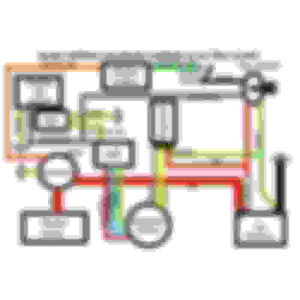
Fact is, it doesn't matter as you can by pass it, a single wire to the lever would indicate it is shorted to earth when the brake is on, so if you short it to earth the starter solenoid should work. Two wires are more likely to mean the wires are connected when you put the brake on, so jump them together and the starter should work. I have just pulled this off the net, the famous bare bones diagram,
the switch marked safety switch is the one in question. Trouble is, does your new harness match the diagram?
Thanks for the information and the diagram. It looks like mine is wired similarly, but has a few more wires than shown. I've played around with it the last few days trying to figure out the bypass you suggested. So far still not working. However, I'm starting to wonder if they sent me the wrong handlebar switch with the harness as it doesn't look like wire colours are matching on each side of the connector. I've tried to mock up a diagram of my wiring harness based on the one you have shown. I also identified where I thought the bypass should occur. Does that look accurate to you? There are also 3 connectors that didn't seem to have a place to go. Are those extra or are there connections that I'm missing to those
. Thanks very much for your time and help.
I put new wiring harnesses in all the time, but I've never seen one with the extra connectors with those color wires. The handlebar switch wire colors never match, but it looks like you have 2 in one of the connectors going to nothing in the other? The bypass is usually a black wire and a yellow with green stripe. Also looks like you have a black with white stripe going to a headlight? Wish I could be more help, but this is a strange one.
I put new wiring harnesses in all the time, but I've never seen one with the extra connectors with those color wires. The handlebar switch wire colors never match, but it looks like you have 2 in one of the connectors going to nothing in the other? The bypass is usually a black wire and a yellow with green stripe. Also looks like you have a black with white stripe going to a headlight? Wish I could be more help, but this is a strange one.
Okay, this is good to know. I'll order another one instead and see if it matches better. I'll update once I have the new one. Thanks for the information.
Hold on, unless you know what you are doing, you are not going to get any wiring harness to work. One odd thing shown on your diagram is a set of wires going to the seat frame, why? Note the red yellow is usually a solenoid wire colour.
Hold on, unless you know what you are doing, you are not going to get any wiring harness to work. One odd thing shown on your diagram is a set of wires going to the seat frame, why? Note the red yellow is usually a solenoid wire colour.
Hello, I haven't altered the wiring harness in anyway and just plugged it into existing connectors that either came with the harness or were already on the quad from the former wiring harness (e.g. headlights, seat frame, etc). The connector on the seat frame was already there on the ATV so I just connected the connector that fit and seemed most logical. Here is what the wire on the frame looks like. It seems to be attached to a rubber of some sort. I thought maybe it was a sensor, but not sure what it would be for. So perhaps I should not attach those wires at all? Thanks for your time and patience.
That black and red wire on the frame is for a battery charger. If you lift the rubber cover there are probably 3 metal prongs for a plug in charger. As merryman said the red/yellow wire usually goes to the solenoid, so the connector you have plugged into it likely goes to the solenoid.
Thanks gents. You were absolutely correct those two wires were the issue. I switched them to the solenoid and now I have power to the starter. Those wires were in an odd place in the harness so that's what confused me. Now just need to get it to actually fire up! Thanks also for the information about the charger receptor - it had 3 prongs just like you noted. Thanks again for the assistance!

 Jun 23, 2023 | 12:41 AM


 Thanks also for the information about the charger receptor - it had 3 prongs just like you noted. Thanks again for the assistance!
