
Sunl 70cc problems
 Apr 19, 2012 | 02:05 PM
#1

Thread Starter
|
Weekend Warrior
Joined: Apr 2012
Posts: 5
Likes: 0
hey guys i have a Sunl 70cc dont really know the year i bought it a few years ago.. It runs fine but the battery was not staying charged because the wiring harness was all messed up and wires were cut from previous owner and it was dying and it would never idle right. well this past week,, i cleaned the carb and but a new inline fuel filter and new fuel lines on, started up fine and idle but the kill switch wouldnt work, so i was reading on here that you had to run a wire from the kill switch to the cdi box and the kill switch worked fine after i did that for about 10 minutes, then i tried it again and it wouldnt start, just would turn over.. so took off the wire from kill switch the the cdi box and still the same thing... now the start button wont work and i have to take a screw driver and touch the starter solenoid posts together to get it to turn over but still wont start.. i ordered and just replace the solenoid and the cdi box thinking they went bad.... but i got nothing.,.. ... help please.... thanks
Apr 20, 2012 | 04:04 PM
#4
Thread Starter
|
Weekend Warrior
Joined: Apr 2012
Posts: 5
Likes: 0
i was getting ready to do a compression test and i decided to make sure i was still getting spark... well now i am not, so i just ordered ignition coil, i am hoping this is why its not starting, will update tomorrow when i get the part..
 Apr 20, 2012 | 05:06 PM
#5
Extreme Pro Rider
Joined: Jun 2009
Posts: 3,224
Likes: 10
From: Texas
don't take this wrong and i hate to be blunt, but if your car was unable to start, would you just throw parts at it? what i mean is a few troubleshooting steps and some multimeter/ohm meter measurements can go along way, save you some frustration, and save you money. now i realize the parts for china quads are cheap, but we're just trying to help. we can go through the ignition switch, the handlebar kill switch, the safety interlocks on the brake handle switch, even the tether kill switch if applicable. could be something as simple as a loose connection, cracked/weathered coil wire, crack in the ceramic insulator on the spark plug, or an inline fuse malfunction. seeing how it's not charging the battery, we'll need to follow LynnEdwards' methods of tracing out the wiring on the stator output, trigger impulse output, and some other items that tie in to that system. he'll be online in a little while.
Apr 20, 2012 | 05:22 PM
#6
Thread Starter
|
Weekend Warrior
Joined: Apr 2012
Posts: 5
Likes: 0
don't take this wrong and i hate to be blunt, but if your car was unable to start, would you just throw parts at it? what i mean is a few troubleshooting steps and some multimeter/ohm meter measurements can go along way, save you some frustration, and save you money. now i realize the parts for china quads are cheap, but we're just trying to help. we can go through the ignition switch, the handlebar kill switch, the safety interlocks on the brake handle switch, even the tether kill switch if applicable. could be something as simple as a loose connection, cracked/weathered coil wire, crack in the ceramic insulator on the spark plug, or an inline fuse malfunction. seeing how it's not charging the battery, we'll need to follow LynnEdwards' methods of tracing out the wiring on the stator output, trigger impulse output, and some other items that tie in to that system. he'll be online in a little while.
Apr 20, 2012 | 11:01 PM
#7

Electrical Expert
Likes High Voltage In The Tub!
Likes High Voltage In The Tub!
Joined: Dec 2008
Posts: 3,260
Likes: 14
From: Tracy, California, USA
i understand were your coming from.. i would not be throwing parts at if they were expensive, so far i have spent $20 on parts and they come from a local shop... if it wasnt for the last owner, he had cut the wiring harness and hacked it up because he didnt want the remote kill switch or alarm on it.. so it was a little hard to wire it all back together.. i will update tomorrow... thanks

The difficulty with throwing parts at the problem is that sometimes the first problem remains (a miswire, or a bad connection for example) and you then install a second bad component. Now there are two problems, which isn't twice as hard to fix - it's more like 10 times as hard. So at least keep track of which parts were your original ones so you can go back to just the original problem.
Maybe, since you have received a problem/hacked quad, there are already two installed problems, and you might have now added a third... I think you see my point. There's nothing wrong with what you did (you might be successful after all), as long as you can go back to the original configuration if this path doesn't succeed.
I assume you have the standard 5 pin CDI? Here is the generic procedure:
Is this a picture of your CDI?
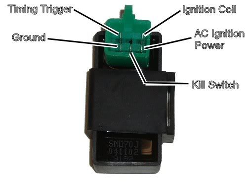
Assuming the answer is yes, the first thing to do is eliminate all kill switches and kill switch wiring:
Method 1) Unplug the CDI and remove the kill switch pin in the CDI connector on the wiring harness. The pin is held in with a spring tab on the pin itself. You'll have to probe into the connector and push this tab in order to extract the pin. Plug the CDI back in (kill switch wire dangling) and see if you have spark.
Method 2) Unplug the CDI. Turn on the ignition switch and set all kill switches to the run position. Use a meter to measure resistance in of the kill switch pin in the wiring harness connector to engine/frame ground. If the resistance is infinite on the 100K ohm scale then your kill switches/kill switch wiring are OK. If you measure zero ohms then you have a kill switch/wiring issue.
The other inputs your CDI needs to make spark are AC Ignition Power, and the Trigger signal. Do the following:
1) Unplug the CDI. In the wiring connector measure the resistance of the AC Ignition Power pin to the Ground pin. You should see 400 ohms or so. What do you measure?
2) Measure the resistance of the Timing/trigger pin to the ground pin. You should measure 150 ohms or so. What do you measure?
3) Leave the CDI unplugged. Set your meter to measure AC volts on the 100 volt scale. Measure the voltage on the AC Ignition Power pin to the ground pin while cranking the engine. You should see 40 to 80 volts AC while the engine is cranking. What do you measure?
4) Set your meter to measure AC volts on the lowest scale you have. Ideally this would be 2 volts but many meters don't go down this low. In that case use the lowest scale you have. Measure the voltage on the Timing Trigger pin to the Ground pin while cranking the engine. You should 0.2 t0 0.4 volts AC. What do you measure?
Now for measuring the output side of the CDI:
A) Leave the CDI unplugged. In the CDI wiring connector measure the resistance of the Ignition Coil pin to the ground pin. You should measure less than 1 ohm (but not zero ohms). What do you measure?
B) Plug the CDI back in. Set your meter to measure AC volts on the 20 volt scale. Set all kill switches to the run position. Crank the engine while measuring the voltage on the Igntition Coil pin to ground. Poke through the insulation of the wire if you can't probe the connector.
Caution: There should be moderately high voltage spikes on this wire. Make sure your fingers are not part of the circuitry. Don't touch the probe lead tips while doing this test.
What you should see is a lot of random numbers with lots of zero values as well. This is because the meter may catch all or part of the spark event voltage, with a lot of nothing in between. Describe what you see.
Note: Using a meter to measure this point produces highly variable results depending on the meter. What you really need is an oscilloscope, but most always a meter is all that is available. We have to do the best we can with what's available. Describe the meter results as accurately as you can - there is information there to chew on....
Trending Topics
Apr 25, 2012 | 09:26 PM
#9
Extreme Pro Rider
Joined: Jun 2009
Posts: 3,224
Likes: 10
From: Texas
i apologize for looking at the mechanical and physical side first . I'm always amazed at Lynn's advice. i need to heed his advice more often on the electrical side
 . but as always, glad you got it going.
. I'm always amazed at Lynn's advice. i need to heed his advice more often on the electrical side. but as always, glad you got it going.

Thread
Thread Starter
Forum
Replies
Last Post
Currently Active Users Viewing This Thread: 1 (0 members and 1 guests)