Avanti 100cc 2006
#1
 11-11-2011, 06:20 AM


Join Date: Jun 2010
Posts: 11
Likes: 0
Received 0 Likes
on
0 Posts
I have a used 100cc quad I just bought. I believe the 2006 Avanti is called an Intruder.The lights come on and the starter turns over. I have no spark.
There is what looks to be a remote cut off (box with antenna wire) on the right side.
Did a search on here for a wiring diagram. Did not see a diagram with the remote cutoff. I want to diagnose the problem and was wondering if anyone has a link to a wiring diagram and a chart of values for voltage and resistance for the electrical components of this Avanti? Thanks
#2
11-11-2011, 11:04 PM

Electrical Expert
Likes High Voltage In The Tub!
Likes High Voltage In The Tub!
Join Date: Dec 2008
Location: Tracy, California, USA
Posts: 3,260
Likes: 0
Received 12 Likes
on
12 Posts
If you really want to talk about remote module wiring we can do that, but I'm suspecting your real problem is "no spark". To eliminate the remote module as the cause you simply need to unplug it. Then it is completely out of the picture. But be aware that there is a minor difference in how the quad operates (assuming this fixes your problem): You will no longer be able to turn off the quad with the ignition switch. You'll have to use the handlebar kill switch instead.
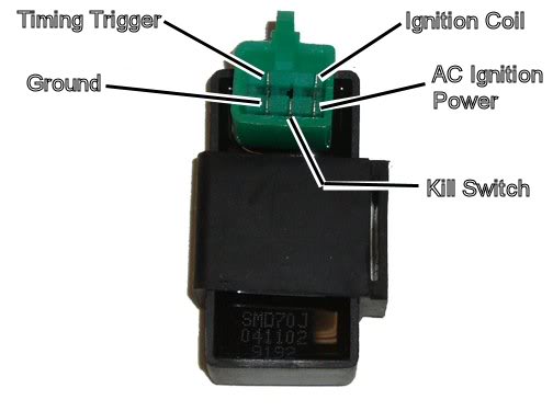
Is your CDI a 5 pin CDI? Like this:
Is your CDI a 5 pin CDI? Like this:
#3
11-12-2011, 08:33 PM
Join Date: Jun 2010
Posts: 11
Likes: 0
Received 0 Likes
on
0 Posts
#4
11-12-2011, 08:54 PM
Join Date: Jun 2010
Posts: 11
Likes: 0
Received 0 Likes
on
0 Posts
#5
11-13-2011, 09:10 PM
Electrical Expert
Likes High Voltage In The Tub!
Likes High Voltage In The Tub!
Join Date: Dec 2008
Location: Tracy, California, USA
Posts: 3,260
Likes: 0
Received 12 Likes
on
12 Posts
I'm not understanding this at all. "Lower left" pin could mean any of the corner pins depending on how you're holding the connector. So we can understand each other could you please use the pin title as detailed in the picture diagram? Then the lower left pin would have a name such as "AC Ignition Power" or "Timing Trigger" which is unambiguous  . Also keep in mind that when you look at the wiring harness connector face it is mirror imaged from the CDI connector picture. Remember you have to flip the wiring harness connector over to plug it into the CDI. So be sure to make that translation when naming pins...
Below is the generic procedure for no spark issues and 5 pin CDI's. Be sure to do all of the tests and provide all of the info. Remember that a meter is not the best piece of test equipment here. A shop would use an oscilloscope for a lot of the measurements, but this is out of reach for the average quad owner. Thus we are forced to use what we have, and the only way to get around some of the meter limitations is measure the same things in different ways, and then combine all the data when analyzing...
. Also keep in mind that when you look at the wiring harness connector face it is mirror imaged from the CDI connector picture. Remember you have to flip the wiring harness connector over to plug it into the CDI. So be sure to make that translation when naming pins...Below is the generic procedure for no spark issues and 5 pin CDI's. Be sure to do all of the tests and provide all of the info. Remember that a meter is not the best piece of test equipment here. A shop would use an oscilloscope for a lot of the measurements, but this is out of reach for the average quad owner. Thus we are forced to use what we have, and the only way to get around some of the meter limitations is measure the same things in different ways, and then combine all the data when analyzing...
Is this a picture of your CDI?

Assuming the answer is yes, the first thing to do is eliminate all kill switches and kill switch wiring:
Method 1) Unplug the CDI and remove the kill switch pin in the CDI connector on the wiring harness. The pin is held in with a spring tab on the pin itself. You'll have to probe into the connector and push this tab in order to extract the pin. Plug the CDI back in (kill switch wire dangling) and see if you have spark.
Method 2) Unplug the CDI. Turn on the ignition switch and set all kill switches to the run position. Use a meter to measure resistance in of the kill switch pin in the wiring harness connector to engine/frame ground. If the reistance is infinite on the 100K ohm scale then your kill switches/kill switch wiring are OK. If you measure zero ohms then you have a kill switch/wiring issue.
The other inputs your CDI needs to make spark are AC Ignition Power, and the Trigger signal. Do the following:
1) Unplug the CDI. In the wiring connector measure the resistance of the AC Ignition Power pin to the Ground pin. You should see 400 ohms or so. What do you measure?
2) Measure the resistance of the Timing/trigger pin to the ground pin. You should measure 150 ohms or so. What do you measure?
3) Leave the CDI unplugged. Set your meter to measure AC volts on the 100 volt scale. Measure the voltage on the AC Ignition Power pin to the ground pin while cranking the engine. You should see 40 to 80 volts AC while the engine is cranking. What do you measure?
4) Set your meter to measure AC volts on the lowest scale you have. Ideally this would be 2 volts but many meters don't go down this low. In that case use the lowest scale you have. Measure the voltage on the Timing Trigger pin to the Ground pin while cranking the engine. You should 0.2 t0 0.4 volts AC. What do you measure?
Now for measuring the output side of the CDI:
A) Leave the CDI unplugged. In the CDI wiring connector measure the resistance of the Ignition Coil pin to the ground pin. You should measure less than 1 ohm (but not zero ohms). What do you measure?
B) Plug the CDI back in. Set your meter to measure AC volts on the 20 volt scale. Set all kill switches to the run position. Crank the engine while measuring the voltage on the Igntition Coil pin to ground. Poke through the insulation of the wire if you can't probe the connector.
Caution: There should be moderately high voltage spikes on this wire. Make sure your fingers are not part of the circuitry. Don't touch the probe lead tips while doing this test.
What you should see is a lot of random numbers with lots of zero values as well. This is because the meter may catch all or part of the spark event voltage, with a lot of nothing in between. Describe what you see.
Note: Using a meter to measure this point produces highly variable results depending on the meter. What you really need is an oscilloscope, but most always a meter is all that is available. We have to do the best we can with what's available. Describe the meter results as accurately as you can - there is information there to chew on....
#6
11-13-2011, 10:01 PM
Join Date: Jun 2010
Posts: 11
Likes: 0
Received 0 Likes
on
0 Posts
#7
11-15-2011, 12:08 AM
Electrical Expert
Likes High Voltage In The Tub!
Likes High Voltage In The Tub!
Join Date: Dec 2008
Location: Tracy, California, USA
Posts: 3,260
Likes: 0
Received 12 Likes
on
12 Posts
1), 2) and 3) look OK. A) looks OK too.
Step "4" is on the low side, and "B" is definitely wrong.
"B" suggest the CDI is not getting triggered, or the CDI is bad. Your trigger voltage is really low, but that could just be your meter. Remember that we are using the meter to do things it was never designed to do. Question: Does you meter read 0.0 volts AC for the trigger voltage when not cranking, and always 0.1 volts AC when the engine is cranking? If so that says suggests there really is a trigger voltage there. That would point more to a bad CDI versus lack of an adequate trigger voltage.
Based on your measured data and it's ambiguous results, I would have to just play the odds. I would change the CDI first, then the ignition coil, then the stator. In terms of likelihood between the ignition coil versus the stator I think the stator wins. but the stator is so much harder to change I would spend 10 dollars to try the ignition coil first. I hope my reasoning makes sense...
Trending Topics
#8
11-27-2011, 06:30 PM
Join Date: Jun 2010
Posts: 11
Likes: 0
Received 0 Likes
on
0 Posts

Thread
Thread Starter
Forum
Replies
Last Post
Currently Active Users Viewing This Thread: 1 (0 members and 1 guests)